Contact Us

Use the form on the right to contact us.

We offer extreme-performance custom flashlights, EDC, and accessories. Home of the world's most powerful production LED thrower with 3 kilometers ANSI throw. 

IMG_20180919_152657237EDITED.jpg

Blog

Keep up with the latest sales, discounts, news, product releases, and projects here on our blog. 

The big test is coming.......

Silent Thunder Ordnance

IMG_20190227_164809656E.jpg

To my knowledge, there has never been a large scale comparative test of moderators like this before, where every design is put on the same exact host and tested on the same meter on the same day. We’re going to do it with a proper meter capable of capturing peak volume as well as generate a sound capture, to provide a more complete look at the moderator’s sound profile, dominant frequency, and so on.

Going from left to right, back to front, we have Wolf Air?, Neil Clague, Neil Clague, 0dB, TKO?, STO experimental, STO experimental, DonnyFL Sumo, Wolf Air?, DonnyFL Tanto, DonnyFL FX, STO Levitas, and Huggett Belita.

The big test is coming soon, watch this space……..

Product Change - Scalpeldashi

Silent Thunder Ordnance

20% carbon fiber reinforced nylon scalpeldashi sheath, seen here next to a figured bubinga scalpeldashi

20% carbon fiber reinforced nylon scalpeldashi sheath, seen here next to a figured bubinga scalpeldashi

Earth shattering news here: all scalpeldashi now come with a sheath. That little announcement just changed your life right? These new included sheaths are 20% carbon fiber reinforced nylon which is durable, cut-resistant, and has an attractive textured finish. The only exceptions to this are the one-offs which are sold with a matched/paired sheath, those do not include a second CFRN sheath.

Airgun Moderator Design, Performance, and Development (part 4)

Silent Thunder Ordnance

FX Crown with Levitas, an ultra light and compact 1/2-20UNF moderator

FX Crown with Levitas, an ultra light and compact 1/2-20UNF moderator

And now for the latest installation in the thrilling adventures of airgun moderator design. You can find part three here. In this episode I test the culmination of quite a lot of designing and testing and tweaking to create an effective 1/2-20 UNF “universal” moderator which I’ve named Levitas, latin for lightness or fleetness of foot. A fitting name for a moderator which is a mere 120mm in length, 35mm in diameter, and 65 grams in weight, but has the sound attenuation of a much heavier and greater volume design. This series started off as a pet project, but I’ve gotten so much interest in moderator design and so many requests for a 1/2 UNF version I decided to build one. So after much time, effort, and refinement, here it is.

Levitas, a 120x35mm 65 gram 1/2UNF moderator.

Levitas, a 120x35mm 65 gram 1/2UNF moderator.

Adapting the original concepts to a 1/2UNF universal application is more challenging than it sounds. The FX Crown's unique design, and unique associated moderator, was more than just a gas diode. The large thread allowed for significant flow to be tapped off from around the bore. Were size no constraint a blast chamber integral to the moderator could be used to fulfill the same function, however this is volumetrically inefficient when it comes to this level of sound attenuation. Further, the lack of a flow-through system along the perimeter will put additional load on the gas diodes as there is no alternate pressure relief, they simply have to eat it. This leads to one final concern, which is air stripping. Without the expectation of some sort of muzzle brake on the rifle to pull turbulent gas off the pellet near the muzzle, the moderator must now possess this as well.


An image of the rev.4 core design clearly showing the three distinct stages. Not shown are the rubber and foam elements which attach to the skeletal structure seen toward the muzzle end of the moderator.

An image of the rev.4 core design clearly showing the three distinct stages. Not shown are the rubber and foam elements which attach to the skeletal structure seen toward the muzzle end of the moderator.

So, how to go about it? Well in this case I went with a three stage system. The first stage is, of course, the aforementioned blast baffle/air stripper. A symmetrical conical baffle designed to bear the brunt of the blast out of the airgun's muzzle, and cleanly strip that turbulent air off the pellet to maximize accuracy. Following that, the second stage, are two of a new and more efficient gas diode which stops or at least delays forward air flow. Unlike the rev.1 and rev.2 gas diodes, which were comparatively volumetrically wasteful, these waste much less of the precious internal space. They also offer cavernous flow-chambers, reflexing vastly more air. All in all, they are a massive design improvement, and I really couldn't be more pleased with them. The third stage is something incorporated all the way back in the rev.2 gas diodes, sound damping. Why should flow and sound in a moderator be the same from end to end? It wouldn't, not if the moderator is working properly anyway, so it stands to reason the design of the moderator itself should change from end to end to match this. Most moderators out there seem to either focus on flow disruption or sound damping, but my approach of first flow stopping then multi-layer sound damping appears to be more effective than either flow stopping or sound damping alone. The CAD images don't capture this sound damping structure well, showing just the skeleton around which is it installed, however it is built of high surface area foam, a new type of foam I’ve never before featured, and rubber. Again this is a combination of materials arrived at after much testing of different combinations and designs.

Before we get to the test results, I also want to bring up something I’ve touched on before, which is peak sound vs. total sound. It is difficult to relate and difficult to quantify, this concept of total sound, because in essence you’re trying to put a number of a squishy human perception. I’ve done a series of experiments with RMS (root mean square), however so far these have not yielded good consistent data. You see there is more to a moderator than just the brief “uncorking” sound produced when the pellet exits and the maximum pressure wave gets out, there is also the sound of your moderator draining that pressure slowly over time. A bare muzzle may have a very high peak, but the subsequent drop back down to zero will be very rapid. Meanwhile a moderator design which effectively slows the flow of air out may have a very quiet peak however because the moderator spends a long time, relatively speaking, draining out all that air until it equalizes with ambient pressure, it may produce more total sound. How this relates to human perception of loudness is more complicated still, because both intensity and duration of sound will affect perception. At longer ranges though it seems the peak is what is most audible, and most likely to alert a prey animal or nosy neighbor. Thus quantifying this is next to impossible, which is why we associate a representative sound readout with each data sample. Below you can see an example in high tech MS-Paint, with the peak (what I measure) circled in purple, while the subsequent sound profile bracketed in teal.

High tech MS-Paint drawing showing what we measure, the peak, outlined in purple as well as a significant but thus far difficult to quantify sound profile bracketed in teal.

High tech MS-Paint drawing showing what we measure, the peak, outlined in purple as well as a significant but thus far difficult to quantify sound profile bracketed in teal.


So enough foreplay, how about test results? I used the same protocol as always, with the moderator separated from the pickup by 1 meter, perpendicular to the muzzle. Excluding the Crown Shroud test, which was done with the shroud extended, all tests were done with the Crown shroud collapsed. I also pulled the old foam filled moderator out to once again provide fair comparison against a “typical” foam/felt filled moderator (your hair curlers and washer baffles) design of equivalent material, design, volume, etc.


Shroud Extended - 214.4

Shroud Extended - 214.4

Shroud Extended - 214.4

Been there, done that. It is loud. It is the baseline, it is what it is. I always insist on repeating the baselines because some days, some atmospheric conditions, god knows some moon phase just results in different numbers. So I always strive to meter the baseline/s so that the later data has good context.

Rev.1 Gas Diode – 122.6

Rev.1 Gas Diode – 122.6

Rev.1 Gas Diode – 122.6

Again, another baseline. The rev.2 is a major design improvement, but it is always good to see progress. Here we can also see one of the things which I strove to improve upon, which is the quantity of noise produced AFTER the peak.

Foam Filled Moderator – 172.4

Foam Filled Moderator – 172.4

Foam Filled Moderator – 172.4

Again, this is an open cell foam filled moderator, intended to be a test analogue for the common high surface area moderators out there which use felt or foam. Here we see a phenomenon I alluded to before, all the way back in the first tests. The sound just tapers faster on these sound damping, rather than flow-stopping, designs. So you get higher peak sounds, the moderator is definitively louder, however it empties that air more quickly and more quietly. We can see that in the image, the initial spike is quite high, but the subsequent taper is more rapid. One has to wonder if part of the reason why felt/foam baffle-less moderator designs are so popular because of this phenomenon: while they may technically be louder, particularly at close range some people may perceive them as quieter. Borrowing or purchasing a popular and highly regarded commercial moderator design, such as a Donny FL, might be a good idea both to get a better understanding of what sound profiles they produce but also to provide a baseline for comparison that other people can relate to.

Rev.2 Gas Diode – 115.3

Rev.2 Gas Diode – 115.3

Rev.2 Gas Diode – 115.3

Still doing comparisons and baselines, what can I say? The second lowest peak, and one of quietest total sound profiles of all the moderator designs tested today. Why? Well this moderator you'll recall is a combination of gas diodes and sound damping in the center, and with off-axis flow-through around the perimeter, again with sound damping toward the muzzle end. The result is a design which slows the initial blast, and effectively and quickly drains the pressure and quiets the resultant sound. Thus there is both a fairly mute peak, and good quick tapering of the remainder of the sound profile.

Levitas (Rev.4 Gas Diode) (1/2-20UNF attachment) – 81.2

Levitas (Rev.4 Gas Diode) (1/2-20UNF attachment) – 81.2

Levitas (Rev.4 Gas Diode) (1/2-20UNF attachment) – 81.2

So this is the culmination of all this testing, the moderator which this is all about. More efficient gas diodes and a sound damping system work together to bring the peak down to the lowest moderator yet tested. And I don't mean just in this round of tests, I mean of all time; this is the quietest airgun shot I’ve ever sampled. I was surprised and pleased, to say the least. Remember this moderator maintains the same overall length, 120mm, as the other designs which ALL were direct thread into the Crown shroud. Integrating a 1/2UNF thread mount means you now have to eat up precious length and volume inside the moderator for the threads, so I would have been exceptionally happy if it were able to simply match the rev.2 gas diode, beating it by a significant margin was an unexpected but pleasant surprise. You'll notice though that the peak is not much higher than the rest of the sound profile. Both of the previous gas diode designs (revs.1&2) had pickups around the perimeter, out of the bore axis, which tapped off gases from inside the Crown Shroud and likewise vented them out of line with the bore. This is more useful than you might think, as it allows you to place dampers directly between the sound source and the exit for at least some of the air. This isn't possible with a 1/2UNF mount, for obvious reasons. While such a design could hypothetically be integrated into the blast chamber, with the loss of volume and effective length it just wasn't feasible thus was omitted. Even still though, it is great performance by any standard, so I'm very happy with it.

What will the next advancement be? Not sure yet, but as long as people find this interesting we’ll keep experimenting. I do want to test other moderators. A dirty secret of the firearm suppressor industry is that values can vary significantly from day to day due to ambient conditions, and my testing shows this is no different with airgun moderators. That said the values are reasonably close enough as to provide a very general basis of comparison, which would be very nice to have. So if anyone has a moderator they would be willing to loan for testing, if it has a 1/2UNF thread I’d be happy to give it whirl. Watch this space!

Comments? Questions? Fire away.

FX Crown with Levitas, an ultra light and compact 1/2-20UNF moderator

FX Crown with Levitas, an ultra light and compact 1/2-20UNF moderator

Project - Arca Swiss to Swivel Stud adapter

Silent Thunder Ordnance

Arca Swiss rail adapter for FX Crown

Arca Swiss rail adapter for FX Crown

This was a quick little pet project to make moderator sound testing more convenient and accuracy testing easier when there is a couple feet of snow on the ground. It is pretty much what it says on the tin, using the sling swivel stud on an FX Crown and adapting that to an Arca Swiss rail interface. This example is entirely 3D printed, but for a 3.5x20mm brass pin which goes through the swivel stud. The clamping force from the tripod head holds everything together. A small window provides access to the front gauge…… assuming the clamp doesn’t obscure it.

This whole thing can be machined or 3D printed, and we’re offering up the 3D digital files if anyone wants/has use of them.

Why Arca Swiss, and why swivel stud? The Harris type bipods attach via a swivel stud, and are very light weight and durable. It is also lower-profile and less marring to use a swivel stud than a rail. Regarding Arca Swiss, they’re the manufacturer of arguably the best monoball tripod head, and in so doing set the standard for mounting clamps. Now most tripod heads use them. Manufacturers in the precision rifle industry are starting to pick up on this, and you’re seeing Arca rails more and more often on chassis systems. Oddly though, it seems a lot less common in the airgun industry.

Project - FX Crown Moderator (part 3)

Silent Thunder Ordnance

FX Crown with carbon fiber gas diode moderator

FX Crown with carbon fiber gas diode moderator

You can find part 2 here. This is the third installment of our attempts to make a novel and effective moderator for the FX Crown, the basis of which is a linear Tesla Gas Diode. The ideal is to generate an extremely compact, light weight, and POI-shift free with exceptional sound attenuation for its size. As an aside, we’ve received a lot of interest about our FX projects. The moderators in particularly have gotten quite some attention. If you have additional questions, please feel free to use the contact form in the top right hand corner of our website to get in touch.

It has been about two months since the last major update, and in that time we’ve gone through a couple different designs, tests, and revisions. Here we finally bring it all together and do one comprehensive analysis of all these evolutions. But first a question:

Why do many if not most moderators have the same architecture from end to end? It didn’t make sense to us either. This concept of flow-stopping at the rear and sound absorbers at the front is really the evolutionary theme with this test, because we have discovered it is very effective. It is more effective than either purely sound absorbing materials or baffles alone. Gas diodes revs.2, and 3 as well as LIM, use this to great effect. You first blunt the air flow with the baffles, and then you mop up the sound with the damping materials, in a manner of speaking anyway. Simple right? Regarding what materials we used, we did a bunch of experiments (not published) on all sorts of things, including several grades of the very popular felt. Ultimately specialty foam and rubber won out across the board, and so that is what was used in all subsequent tests.

Sound analysis

Same standard protocol and data capture/averaging as in the second test, although we switched pellets to JSB 18.13gn for this test. I do want to note quickly that atmospheric conditions, minute variations in the setup, pellet choice, and about a dozen other things will affect readings, which is why we retest our baselines EVERY SINGLE TIME. It is also why these numbers completely don’t line up with previous test numbers, as we wouldn’t expect them to and weren’t trying to make them. Conditions were about 31 degrees Fahrenheit, sunny, and with a light breeze.

FX Crown with shroud extended.

FX Crown with shroud extended.

Stock Shroud Extended - 199.6

About what you’d expect here, obviously the loudest test. You can once again see the sound bouncing forward and backward in the tube as well. We’ve seen this all before.


The OG gas diode from our first test. Exceptional sound attenuation for its size and weight.

The OG gas diode from our first test. Exceptional sound attenuation for its size and weight.

Tesla Gas Diode rev.1 - 138.2

This is our OG gas diode from the first test, the silver one for those paying close attention. As before, it extends the time frame where noise is observed, as well as blunting the initial peak. Not much else to say that hasn’t been said before. I don’t have a hypothesis about what that small initial positive peak is, it seems too close to the uncorking event to be the hammer slapping the valve, however I’d guess they are some other mechanical function of the gun. Either way, in this sample, it is very visible thus noted here.

An image of the core of our rev.1 flow-through gas diode

An image of the core of our rev.1 flow-through gas diode


Tesla gas diode rev.2, amazingly it is even quieter and lighter than rev.1

Tesla gas diode rev.2, amazingly it is even quieter and lighter than rev.1

Tesla Gas Diode rev.2 - 112.0

The original gas diode had exceptional performance for its size and weight. What if you could cut that weight down by an additional 11% though, bringing it down to just 57 grams, all while attenuating sound even further? That is the concept which brought forward rev.2. It is still flow through, and still uses linear Tesla gas diodes at the rear, but after the diodes blunt the forward movement of the air, we applied sound attenuating materials so the subsequent draining of pressure out the muzzle end was even quieter. And it clearly worked. Beyond just lowering the peak output, it reduced the post-peak sound in both volume and duration. For people using cheap sound meters which can’t capture the peak, or cell-phone apps, this is probably what they’re measuring anyway. Regarding the core design, it is difficult to effectively show as it is a multi-part assembly which isn’t conducive to cross-sectioning in CAD. In brief though, at the rear, are the same flow-through structures on the outside and gas diodes in the core. Beyond that is a skeletal structure onto which the foam and rubber are installed. The same flow-through vortex cap as rev.1 is used at the muzzle end.

Rev.2 gas diode moderator. Not seen is the foam and rubber which populates the skeletal section at left, and further mutes the report.

Rev.2 gas diode moderator. Not seen is the foam and rubber which populates the skeletal section at left, and further mutes the report.


Rev. 3 gas diode

Rev. 3 gas diode

Tesla Gas Diode rev.3 - 100.6

Like rev.2, this design uses gas diodes at the rear and a foam and rubber damper at the front. The major changes though are larger diodes, so no flow-through and a solid cap, along with a more aggressive rubber and foam section. It is a great design, but there are a few tweaks it could benefit from in regards to the damping section. We’ll get to the why of that in the next section, but suffice to say its minor improvement in sound attenuation is likely both caused and offset by some issues with the damper section. There is good reason to pursue this design further though, because the lack of flow-through means it could be redesigned for use on guns other than the crown, something we’ve gotten a lot of requests for. It is also worth noting that scale is a challenge with the rev.1 and rev.2 gas diodes, they are about as small as is possible without a major equipment reconfiguration. Omitting the exterior flow-through section has allowed these diodes to grow, which has other potential benefits.

Rev.3 gas diode. Not seen, but which would be to the right, is the foam and rubber assembly which acts after the gas diodes. This design uses a different cap (not pictured) as it is not flow-through.

Rev.3 gas diode. Not seen, but which would be to the right, is the foam and rubber assembly which acts after the gas diodes. This design uses a different cap (not pictured) as it is not flow-through.


LIM moderator sound profile

LIM moderator sound profile

LIM - 91.2

LIM stands for Less Is More, the concept being maximum usable volume and a minimalistic design. It uses the same post-baffle dampers (not pictured) as the rev.3 gas diode. And I mean quite literally the exact same, we just swapped that section of the moderator for testing. The image below is actually outdated, as the baffle design has since been tweaked, however for now this design is a dead end. Why? Well moderator design is a balance between silence and accuracy-disrupting turbulence. In this case in its less-turbulent guise it was louder, and still caused accuracy issues, and in this test format it creates even more significant accuracy disruption but is a bit quieter. And that is really all there is to say about it.

LIM moderator core. This uses the same damper assembly and cap as the rev.3 gas diode. Unfortunately this design appears to be a dead end, as it induces accuracy issues.

LIM moderator core. This uses the same damper assembly and cap as the rev.3 gas diode. Unfortunately this design appears to be a dead end, as it induces accuracy issues.


If you’ll forgive the hasty scrawl, here is a quick target to confirm whether or not a design has accuracy issues. Note that LIM shows only 4 rounds, as it threw a flier so bad it was entirely off the paper.

If you’ll forgive the hasty scrawl, here is a quick target to confirm whether or not a design has accuracy issues. Note that LIM shows only 4 rounds, as it threw a flier so bad it was entirely off the paper.

Accuracy Analysis

Knowing that moderators, particularly overzealous ones, have a nasty habit of messing with accuracy, it is important to shoot some quick groups to ensure everything is working as it should. These groups were shot standing off a tripod which, if you’ve never done it, is more stable than hand holding but less stable than prone with a bipod. The range was 59 yards, the temperature was 31 degrees Fahrenheit, and there was a gentle breeze moving both the pellets and the target itself. Groups are all 5 rounds. It is worth noting that some of the shots tear the paper, and they have a tendency to tear it downward, but this is not keyholing I can assure you. Sighters were taken on another sheet, not shown here.

The rev.1 gas diode has already been extensively shot, so no need to revisit that here. So I started with the stock shroud as a baseline, which produced an extreme CTC distance of .67”.

The rev.2 diode did well, as expected, no notable POI shift and it was just a whisker over 1MOA here at .63” CTC. Omit the one high round, and it shrinks to .49”CTC. Certainly no accuracy issues here, and this design has been tested a bit before and should have no issue.

The rev.3 gas diode didn’t do as well, at .85” CTC, however this was almost certainly due, not to the diodes, but to too aggressive a foam and rubber damper section. The same issue reared its ugly head with the LIM which actually managed to suck some of the foam into the flight path, have it be trimmed by the pellet, and spit it out producing a flier which was off the paper. The less disruptive rev.3 diode didn’t send a pellet that wild, but clearly the damper section needs to be scaled back. This will cut sound attenuation to some extent, but will cure the accuracy issues.

LIM is just straight out. One round was off so far it missed the entire paper. Beyond that, the 1.07” CTC was less than inspiring, as was the POI shift. It serves as a great demo though regarding how a moderator can be made significantly quieter at the expense of accuracy.

And that is it for part 3. If this series continues to attract interest there will likely be a part 4. Let us know what you’re curious to see.

FX Crown with carbon fiber gas diode moderator

FX Crown with carbon fiber gas diode moderator

Project - FX Crown Magazine; Fixing The Fliers

Silent Thunder Ordnance

FX Crown magazine, 3D printed, in .22 caliber. The name of the game is to create clearance for the pellet skirts so that there is a lower propensity for fliers than with the stock magazine.

FX Crown magazine, 3D printed, in .22 caliber. The name of the game is to create clearance for the pellet skirts so that there is a lower propensity for fliers than with the stock magazine.

It seems we’ve got a bit of a theme going here with FX Crown projects. People seem to like them though, so we’ll keep going.

The problem de jour is the magazines. We’ve already touched on this with our FX Crown Single Shot Tray post. The long and short of it though is, at least with the Crown, if you use a single shot tray you’ll notice a lot fewer fliers and your groups will tighten up. Why? Obviously something about the magazine is damaging the pellets.

My hypothesis is that the damage is being done to the skirts. There are three reasons for this. First is obvious, the skirt is the most delicate part of the pellet. The second is that the skirts on JSB pellets is actually significantly larger diameter than the pellet head. This is done, presumably, to maximize gas seal. But, and here comes number three, FX magazines are designed and machined essentially in 2.5D, that is to say straight and square vertical walls. This means they are easy and fast for FX to manufacture on a 3 axis CNC milling machine, but it also means that as the magazine snickity-snacks from one index to the next, the pellets are being shoved around and stopped, not on their more robust heads, but on their delicate skirts. Obviously that isn’t a win.

First off, credit where it is due to rj2239 for being the inspiration for this project. I initially sank my teeth into this hearing the MISTAKEN assertion on the forums that a Crown magazine is just a mirrored Impact magazine. Let me dispel this myth now, they’re not. They are very very similar, but are not the same in just a few critical tolerances. This stands in contrast to the FX Dreamline which FX claims will use an identical magazine to the FX Crown. Hopefully then this project can benefit FX Dreamline buyers as well. Regardless, even though I only used rj2239’s follower (and may still redesign that), the half dozen clever little fixes and small parts links were all invaluable to getting this done. So kudos and thank you.

So what did I change? Well the concept is quite simple: if the skirts are wider than the heads, provide clearance in the magazine for the skirts. This way the pellets are pushed around by their heads not their skirts. Aside from building the mag to Crown dimensions rather than Impact dimensions, the other minor change I made was to the support structure for the alignment slot. I’m not sure what printing technology, or clean-up methodology, rj2239 was using, however when printing his designs I essentially gave up cleaning that out by hand and started cutting the slots with a mill. Most people don’t have access to those sorts of tools, so a simple rethink of the supports in that area so it could be easily cleaned up with a fine knife such as a Scalpeldashi. (shameless plug, but it is what I used. I carry one for a reason.)

So by this point you’re asking how to get your hands on one of these magazines. We’re giving away the design files for free, so they can easily be 3D printed. Figure they’re worth what you paid for them, all humor intended. For those so inclined who want a transparent face cover, and don’t have access to a laser cutter, we’ll also sell you the raw cut acrylic face plates.

How to go about converting all this into a magazine, and what do you need?

Tools you’ll need at bare minimum:
3D Printer
Metric Hex Keys
Scalpel (or equivalent small sharp blade)
File
Needle Nose Pliers
Superglue

You would additionally benefit from/ideally own:
Quality ABS filament (as opposed to PLA)
Acrylic Face Plate (transparent)
Drill Press
Drill Index
Acetone
Hacksaw
Threadlocker
Squeeze clamp

Parts (all links go to Amazon for convenience, however they can be sourced anywhere):
M1.5x3 O-ring (3mmID, 1.5mmWD)
M3x5 Brass Insert
M3x3 Grub Screw
M3x10 Countersink Screw
2mm Brass Rod
Spring (from retractable badge)


Step one: print the parts. If you’re going to use one of our clear acrylic covers, you only need to print the magazine body and magazine follower. If you aren’t, you’ll want to do the face plate as well, perhaps in something transparently/translucent. It is a free country and all, but I would recommend you double check your printer’s calibration first and use a fairly fine layer height.


Step two: clean up everything. Clean up the alignment slot on the bottom of the magazine body (I use a Scalpeldashi for this with a #11 blade), and clean up all the edges. Also, if you have a round file of the right diameter, it can be invaluable in cleaning up the magazine follower.


Step three: dry-fit. Dry fit the magazine body and face plate in the gun to make sure in step two you cleaned up that alignment slot correctly so that the bolt-probe clears and your overall thickness is good.


Step four: acetone. SEPARATELY dip the magazine body, follower, and if printed the face plate in acetone. (don’t dip an acrylic face plate, seriously) Allow them 24 hours to cure before moving to the next step.


Step five: drill critical tolerances. If you don’t have a drill index, you’ll want to fudge this step using whatever tools you have available, a scalpel blade being the most likely candidate. The following parts should be bored to the following dimensions:
Follower - 29/64” (will vary, in some cases significantly, based on material and print settings)
Magazine center through hole - #31 drill bit
Magazine center to shoulder (blind, for brass insert) - #4 drill bit
Magazine corner (grub screw) - #39 drill bit


Step six: assembly and final dry-fit. Dry fit everything together excluding the spring. Install the brass bushing by pressing it through from the back. Insert the grub screw in the corner, and thread it in. (this can be done backwards to make it faster/easier) Cut off a little brass rod piece and and glue it in the hole in the face plate. Glue an o-ring in the blind hole in the face plate. Place an o-ring in the center pillar of the magazine so it generates friction between the magazine body and face plate when the two rotate relative to each other. Test that the follower rotates freely, add a drop of pure silicone oil or wax if desired. Check manually for pellet and probe clearance, feed, and function under no spring load.


Step seven: install the mainspring. Break open one of the ID badges and remove the spring. If the ends aren’t correctly bent to install in the magazine, bend/cut them now. I personally find it easier to install the magazine body end of the spring first, then coil it around the central pillar and use a squeeze clamp as a “third hand” to hold the spring while installing the follower end. Needle nose pliers are invaluable here. Remember this spring will act much like a constant force spring, so getting the absolute maximum possible number of coils around there won’t significantly increase spring pressure. Apply a drop of pure silicone oil to the spring, and test for function.


Step eight: Assemble the magazine fully and test one last time.


Step nine: Add a hind of threadlocker to the center screw, tension the face-plate as desired, and allow to cure for 24 hours.

And you’re done. Enjoy! I shoot this magazine personally, so the design may be updated from time to time as I make improvements.


Project - Dope Card Holder

Silent Thunder Ordnance

FX Crown with an 11mm dovetail DOPE card.

FX Crown with an 11mm dovetail DOPE card.

So when we hunt with airguns, there are four common threads:

Night vision image of another local night predator.

Night vision image of another local night predator.

  • We hunt around a series of targets/stations from a known position

  • Targets are pre-ranged, and often pre-shot, so that the hold is known

  • Often this is done at night, when re-ranging/shooting a target to test hold is inconvenient at best

  • We’re forgetful and with half a dozen targets, you’re always double-checking your DOPE sheet to make sure you have the right hold for the right target

A DOPE card holder designed to attach to 11mm dovetail is the obvious solution. A few additional design requirements/caveats were that we wanted something easy on-easy off with just one tool, we wanted a flex mount to handle recoil and getting banged/caught on things, we wanted a card backer which could be exchanged to different sizes but also directly written on, and we wanted a non-destructive break-away feature so that when you inevitably catch it on something hard it doesn’t cause any damage to the rifle or itself.

Prototype 11mm dovetail DOPE card.

Prototype 11mm dovetail DOPE card.

The original design, seen at left, was a bit chunky and long, adding unnecessary length to the whole system.

The final version is slightly more clever, cutting the length significantly, and made up of just seven components. It slips easily on and off a dovetail rail with just a slotted screwdriver or coin, the center is a piece of flex tubing which bends to absorb recoil and can be pulled off if hit/caught on something. The card backer itself is 1/8” thick, and while black is pictured, transparent is also easy. Clipping a notecard to the backer using a binder-clip, the more common strategy, is also easy as this thickness works well with the small binder clips.

We may update this concept over time. One possible avenue is to replace the card backer with a sheet of a glow-in-the-dark material, such as moonglow, to make it readable in pitch black conditions. Tritium illumination is also a distinct possibility.

FX Crown with 11mm dovetail DOPE card.

FX Crown with 11mm dovetail DOPE card.

Out of Office 11/22/18 - 11/25/18

Silent Thunder Ordnance

We will be out of the office for the Thanksgiving holiday, 11/22/18 - 11/25/18, so will be unable to ship orders or respond to inquiries. During this time we’ll have the coupon code TURKEY2018 active, so customers who enter it at checkout can get a 5% discount on all orders. Happy holidays everyone!

Project - FX Crown Moderator (part 2)

Silent Thunder Ordnance

Tesla Gas Diode Moderator on the front of an FX Crown .22 synthetic with athalon argos optic

Tesla Gas Diode Moderator on the front of an FX Crown .22 synthetic with athalon argos optic

You can find part 1 here. This is the second installment of trying to make a novel and effective moderator for the FX Crown based around the concept of a linear Tesla Gas Diode.

Cutaway of the Tesla Gas Diode design

Cutaway of the Tesla Gas Diode design

Having successfully designed and built one, I also built several other designs of various industry standards to compare it against. Those are the common felt/foam from the airgun industry and the clipped conical baffle design common to the suppressor industry (with flow-through around the outside). All that remained was to test them and compare.

Cutaway of the clipped conical baffle design. Note the blast baffle is un-clipped to minimize POI shift.

Cutaway of the clipped conical baffle design. Note the blast baffle is un-clipped to minimize POI shift.

So measurement-wise, I went with the suppressor industry standard which is 1.6 meters off the ground, and muzzle 1 meter from the mic. This is done with two tripods, one holding the pickups the other justifying the muzzle of the gun. This assures things are the same every time. Consistency is close to godliness, and if your data is a mess good luck getting anything useful from it. The gun is my FX Crown .22 shooting Crossman Premier HPs, and while I didn't chrono the Crossmans it spits JSB 18.13s at 874fps with +/-3FPS on average. Each configuration was fired 5 times. Six configurations total were tested and they are as follows:

Shroud Collapsed
Shroud Extended
Copper Gas Diode (copper references color, not material)
Silver Gas Diode
Clipped Conical Flow-Through
Foam


Here is what a typical sound data sampling looks like:

Sound sampling from an FX Crown with the shroud extended. Note the secondary peak. This peak appears to correspond to the length of the shroud at the speed of sound. Funny eh?

Sound sampling from an FX Crown with the shroud extended. Note the secondary peak. This peak appears to correspond to the length of the shroud at the speed of sound. Funny eh?

Aside from having exceptional sampling resolution, 250MSa/s that is to say 250000000 samples per second making it able to sample very very brief sound occurrence, it also can provide other interpreted data such as the most prevalent frequency, the overall length and shape of the event, etc. It is very handy, particularly when developing moderators rather than just comparing them. As you can see each sample has a LOT of data in it, multiple channels, the full spicy chalupa. The result is that, rather than a typical sound meter which is sampling one event one time, each value I present below represents multiple simultaneous samplings of each event (a shot), that event is then repeated (five times per configuration, five shots), and it all is recorded. The result is that there is an immense amount of data generated here, and then has to be post-processed, which is all ultimately distilled down into a single average of the multiple samplings of multiple events. Because my calibration is well out of date, rather than then converting to decibels which would be wrong, I just left them as unit-less numbers. This is perfectly fine for the purposes of this comparison, since I doubt anyone else is running a Bruel & Kjaer to produce assuredly accurate numbers anyway. I realize it is all a bit complicated, but hopefully the single value makes it easy and simple. Side note, these aren't powder burners, so there is no first round pop, and because regs are imperfect on the first shot after storage the gun was cycled to “warm it up” prior to testing.

Less handy were the two el-cheapo meters I had running. I've seen a lot of people taking measurements on airguns and posting it on youtube with these inexpensive meters. When last I did this it was with firearms, and years ago, so I thought maybe just MAYBE newer meters had the resolution and range to measure airguns. Several reviews on the new meter I picked up even said that it "worked great on airguns," one even claimed it compared favorably to an "expensive German meter" on airguns. While I can't speak for every meter out there, having done the testing I can now confidently say that this is not the case on this meter at least, and that while the meter will pop SOME number in response to every shot, and they're remarkably consistent, whatever it is reading isn't the muzzle report. How do I know this? Because every single configuration was within margin of error of each other. That meter claimed every configuration was about 97db average. EVERY. SINGLE. ONE. I don't know what it was reading, but it sure wasn't the muzzle. *shrug*


FX Crown muzzle blast with the shroud collapsed. Very very loud, for an airgun anyway.

FX Crown muzzle blast with the shroud collapsed. Very very loud, for an airgun anyway.

Shroud Collapsed - 728
Pretty much what you'd expect here, or rather if you own a Crown, exactly what you've come to know and love. That predictable loud bark. This is easily the loudest test in this series. And it is quite messy, again as you'd expect, because there really is no damping or anything of the sort. Presumably that pressure wave can ricochet up and down the shroud as many times as it wants puffing out the muzzle bit by bit. I'm guessing, just guessing, that the brake and shroud cap act as one in the collapsed position, so there really is nothing here just a reflective tube at both ends. It is possible that by modifying the action end of the shroud stop some significant gains could be seen here, so it isn't just a big sounding tube. Dampers like this could be designed for dual effect, to both eat barrel vibration (improve accuracy) and sound. This might be worth exploring, along with perhaps venting the rear of the Crown shroud...... or alternately replacing the stock shroud entirely with a lighter weight carbon fiber one that is an integral part of the entire sound damping and accurizing strategy.

FX Crown w/ shroud extended

FX Crown w/ shroud extended

Shroud Extended - 312
Again what you'd expect. It is considerably quieter than the shroud collapsed both because of greater muzzle-forward volume, and it tapers more rapidly because the brake now can act as a choke point between the two chambers as the pressure wave bounces forward and backward. Notice the secondary spike in there. A little napkin math correlates this with the speed of sound traveling the length of the shroud. Cool stuff huh? It is possible, given a longer sampling time, we'd have seen more descending spikes tapering off.

FX Crown w/ clipped conical baffle moderator design.

FX Crown w/ clipped conical baffle moderator design.

Clipped Conical Flow-Through - 346
So this was kind of a flow-through outer shell take on the suppressor industry standard of the clipped conical baffle. The clipping diverts flow laterally, making it quieter than your typical symmetrical conical baffle, however it comes with POI shift as I discovered..... in fact over 4 MILs of “repeatable” POI shift. There were two problems with this though, the first that is in pellets this kind of POI shift is destabilizing so it'll cost you some accuracy (unacceptable), and second the crown's shroud is free rotating so any repeatability is also thrown out the window. Hence I didn't do a second pure clipped conical design, because whats the point? Speaking of whats the point, after looking at the numbers you'd have to ask whats the point of this design? It is quieter than the shroud extended, but not by a lot. Given that it is physically the longest design tested by a few milimeters, and has the most baffles, I think we can pass on this conical baffle design for further exploration. It is easy to machine though, so I can see why it is popular.


FX Crown w/ foam moderator. Note the high initial spike and relatively clean sound thereafter.

FX Crown w/ foam moderator. Note the high initial spike and relatively clean sound thereafter.

Foam Fill - 204
Now things are getting interesting. This is my attempt at good performance analogue for the all-too-common foam/felt hair curlers and washer baffles design. It is a relatively thin layer of foam constrained toward the outer surface of the suppressor and exposes maximum surface area, more than the Weilrauch's design. The muzzle end uses the same cap design as all the others, and the threaded rear uses the same flow-through design. To the ear, both my friend and I agreed this design could be the quietest of all six tests. It is hard to tell with these things, so we both were eager to see the numbers, but we both bet that this would win.... somewhat to my chagrin. Looking at the pressure wave, it is very obvious how it peaks very strongly and cleanly initially, and tapers off very quickly. This could be thought of as the visual equivalent of a clean sound moderator, pop and done. We'll get back to this, it becomes important later.


FX Crown w/ gas diode moderator

FX Crown w/ gas diode moderator

Gas Diodes
Cu - 192
Ag - 194
I combined these, as they're identical designs in essentially identical materials. (just differing color) In essence, they should be the same, and testing bore that out. It is always nice though when something pans out, in this case repeatable manufacturing being repeatable and performing consistently. By now you've seen that the numbers are lower, so the moderator is in fact quieter! All my crazy scheming worked. Why then did we both think the foamie was quieter? Remember when I said the human ear is really bad at judging sound pressure level? Well that certainly has something to do with it, your ear just can't tell what is louder than what very effectively, in much the same way your eye can't easily judge how heavy a cow is but a scale can do it accurately all day every day. There is another element I think is at play here though. The foamie had a higher initial spike, with no complex architecture to retard it, however once that passed through it tapered rapidly. The gas diode conversely shows that it is doing EXACTLY what it is supposed to be doing: extending the length of the event by holding that pressure and releasing it slowly. This means it produces sound for longer, which is a good way to fool an ear into thinking something is louder. A hammer hitting a nail doesn't sound that loud, but make something that loud continuous and you'll find it deafening. While that is an extreme example, it illustrates the point quite nicely how something which is quieter but lasts a little longer can sound about the same or even slightly louder than something which is technically louder than it is.


Exterior of gas diode flow-through area.

Exterior of gas diode flow-through area.

So there it is, in its full spicy glory. As with everything in life and science, the answer only raises more questions, more avenues of inquiry. But for now I've accomplished what I set out to do, and to my pleasure and surprise the countless hours of designing and testing and revising all built on a harebrained idea borrowed from the eccentric genius Nikola Tesla from a century and a half ago.

Project - Copper Weaver Slingshot

Silent Thunder Ordnance

Two of our weaver slingshots in polished copper

Two of our weaver slingshots in polished copper

The title pretty much covers it. Two of our Weaver slingshots in polished copper. One is deliberately smoother, while the other intentionally shows off details like the contour lines.

Project - FX Crown Single Shot Tray

Silent Thunder Ordnance

FX Crown Single Shot Tray.PNG

After our last epic saga of airgun moderator design, this one should be a quick hit: a single shot tray for the FX Crown. Retained by an O-ring (just like the factory mags), this is the very common angled-ramp design but with a twist. That twist is rails in the profile of the pellet, in this case a JSB 18.13 grain .22 caliber, to ensure pellet alignment as it rolls down the ramp. Simple and effective.

FX Crown Single Shot Tray pellet.PNG

Project - FX Crown Moderator

Silent Thunder Ordnance

FX Crown with a flow-through tesla gas diode suppressor.

FX Crown with a flow-through tesla gas diode suppressor.

Thanks to a legal ruling, airgun moderators are legal in the United States. This is probably why essentially all airguns now come with one. For most users though, the stock moderator is insufficient to achieve the level of suppression they desire. This was the case with my FX Crown. Strap in, this is going to be a long one. Not sure if you want to suffer through so many lines of crawling ants? Read the conclusion (final paragraph) first, and then decide if you want to know more about the journey that lead to the destination.

In another life, I did design work on firearm suppressors. Experience tells me they are deceptively simple devices; the devil really is in the details. And this runs the gamut from effects on accuracy, size constraints, sound attenuation, and tone. Given huge suppressor volume, it is relatively easy to build something quiet, so the most significant trick is making a quiet design small. The second trick though is accuracy, many extremely quiet designs cause some level of projectile destabilization and associated inaccuracy. Making a complete package which is desirable and effective is just the sort of fun challenge I’m all about.

Enter the FX Crown. Great gun, but even with the shroud extended it has quite a bark (and looks goofy). Airgun moderators have several distinct advantages and disadvantages over firearm ones. The most notable disadvantage is that the projectiles are lighter, have lower sectional density, are more subject to turbulence, and all this makes them easier to destabilize. That is the hard part. The easy part is that the exhaust gasses are cool and the total system pressure and volume at the muzzle are relatively low. This opens up a LOT more materials and manufacturing technologies. It also means moderators can be much lighter weight. The Final major advantage is the legality of airgun moderators, making complete units, parts, etc all much easier to handle.

Original Tesla Fluid Valve patent ref. en.wikipedia.org/wiki/Tesla_valve

Original Tesla Fluid Valve patent ref. en.wikipedia.org/wiki/Tesla_valve

The FX Crown has a somewhat unusual design which provides its own challenges and opportunities. For those unaware, there is a muzzle brake attached to the end of the barrel, and any moderator must be screwed not to this but to the shroud which surrounds it. This means you already have your blast baffle taken care of, as well as an existant pressure reservoir to deal with. It so means your thread will be the unique M27x1.5, not exactly an every day size. An idea I’d long kicked around but never tested was that of the Tesla Gas Diode. A diode is essentially something which allows free movement in one direction, and resists movement in the other. A common use everyone is likely familiar with is the LED or Light Emitting Diode, which is a one-way valve for electrons that produces light as a side effect. While the original design was for fluid only, and didn’t need anything to pass down the bore, in theory it could be readily adapted to be radially symmetric and have a straight bore large enough to pass a projectile. The concept simply splits and reflexes gas back on itself to create resistance which scales, the harder you blow the more it resists. Thus the idea is to restrict the forward flow of gas from the muzzle of the airgun, while allowing it to freely travel rearward back toward the barrel.

The flow-through gas diode suppressor concept, clearly showing the internal chambers where the gas is reflexed back on itself to limit flow. Also visible in this cross section, at the extreme rear, are two of the eight flow tubes which pick up air f…

The flow-through gas diode suppressor concept, clearly showing the internal chambers where the gas is reflexed back on itself to limit flow. Also visible in this cross section, at the extreme rear, are two of the eight flow tubes which pick up air from the rear of the moderator and jet it around the outside.

There is a second element to my design hypothesis here though. Suppressors are all stuck at a general performance class based on size, as that size is the total volume; no matter how efficient your suppressor is, you can only eat as much gas as your can’s volume….. or can you? OSS has popularized this concept recently, although Brugger and Thomet to my knowledge is its originator, predating OSS by well over a decade. The latter doesn’t really publicize their work in the United States or really much at all to my knowledge, and while the former does their designs (to put it bluntly) are way too large, heavy, and loud to be relevant or even demonstrate the forward-vented-volume concept. Their marketing is not centered around sound attenuation, but minimizing backpressure in automatic weapon actions, and to put it politely I believe them. There are a few other users of non-fixed-volume designs in airguns. Air Arms has, at least for the last few years, cut vents into their actions where the shroud meets. These create quite the startling blast to your spotter or anyone else next to you. Huggett also has moderators with mesh screens and vents over the blast area, although their cores are simply a felt/foam/whatever material over a rigid structure to protect it, very similar to DonnyFL designs.

The outer flow path. Visible at the top left, on the toroidal mating face, are the vents which will dump air into this area. Essentially everything visible here will be covered when the moderator is in use, as it slips into a carbon tube and is capp…

The outer flow path. Visible at the top left, on the toroidal mating face, are the vents which will dump air into this area. Essentially everything visible here will be covered when the moderator is in use, as it slips into a carbon tube and is capped.

So I wanted an unlimited volume design, something which will continuously vent gas to increase its efficiency. It is comparatively easy to disrupt a pressure wave if you can physically obstruct it. So to take some pressure, pun intended, off the linear gas diodes I wanted to create an outer chamber inside the suppressor which would allow relatively free flow of gas, while breaking up the pressure front, to allow a small moderator to ingest a lot of flow with minimal sound. Because of the size of the threading, we actually have room to pick up this gas at the very rear of the moderator, essentially tapping it off after the blast baffle courtesy of FX. This is the second half of the concept, once gas pressure has equalized in a given section it will vent more effectively rearward toward the gun, which will will then be taken up by the outer flow tubes and pass through the outer suppressor chamber. This outer chamber requires no in-line flow, so can effectively disrupt the sound. The outer chamber itself is sealed by the tube, in this case a carbon fiber tube. Mating surfaces at the rear and cap are toroidal, which automatically produces alignment with the ends of the carbon tube. This leads nicely to the muzzle cap.

Cap design is its own entire area of study. While they seem simple, a cap can have a significant affect on the propagation of sound out of the loud end. Typically disruptors and channels on the surface are desirable, to redirect sound forward and to break up any wave fronts which emerge, however for the purposes of this initial testing I wanted to use a simple cap design which wouldn’t advantage or disadvantage a particular design, and also minimized overall length. Furthermore, caps being readily exchanged, I can swap this trivially later.

A simple cap. Venting along the perimeter, and a hole for the pellet in the middle. This design uses the same tool for installation/removal as the factory FX shroud.

A simple cap. Venting along the perimeter, and a hole for the pellet in the middle. This design uses the same tool for installation/removal as the factory FX shroud.

For the flow-through designs the cap is quite simple. Threaded at the end, it screws to the front of the core creating a semi-seal. Outside that there are six holes of equal size and spacing to FX’s original shroud cap, so whatever tool was used to remove that can be used to install this. These are through-holes so as to provide further breathing for the outer chamber, although that is a secondary function. The outer line of holes are oval in aperture, but have an offset path. De-torquing of airgun moderators from firing cycles isn’t an issue, however this will serve to generate torque assuring everything remains tight. It will also act as one final disruption of the air as it exits. Simple to implement, and potentially advantageous. The rear face that mates with the carbon tube is, as mentioned previously, is toroidal as this naturally produces good contact and alignment.

Here we can see the offset path of the outer vents, which serve to swirl the gasses as they exit the moderator.

Here we can see the offset path of the outer vents, which serve to swirl the gasses as they exit the moderator.

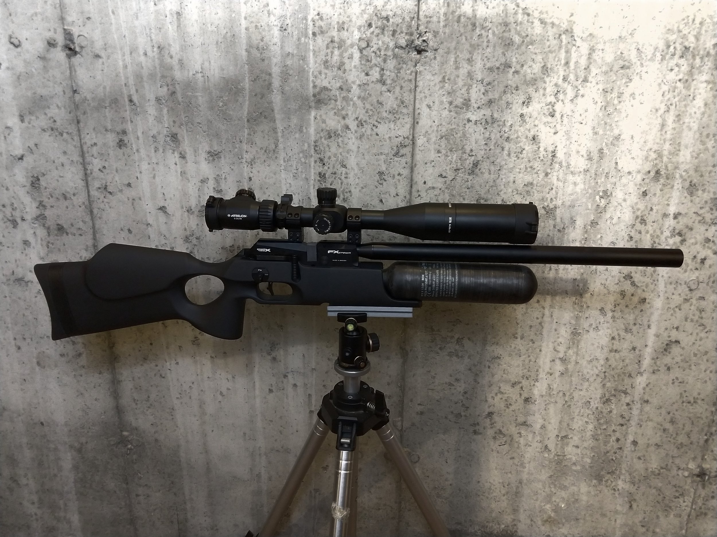
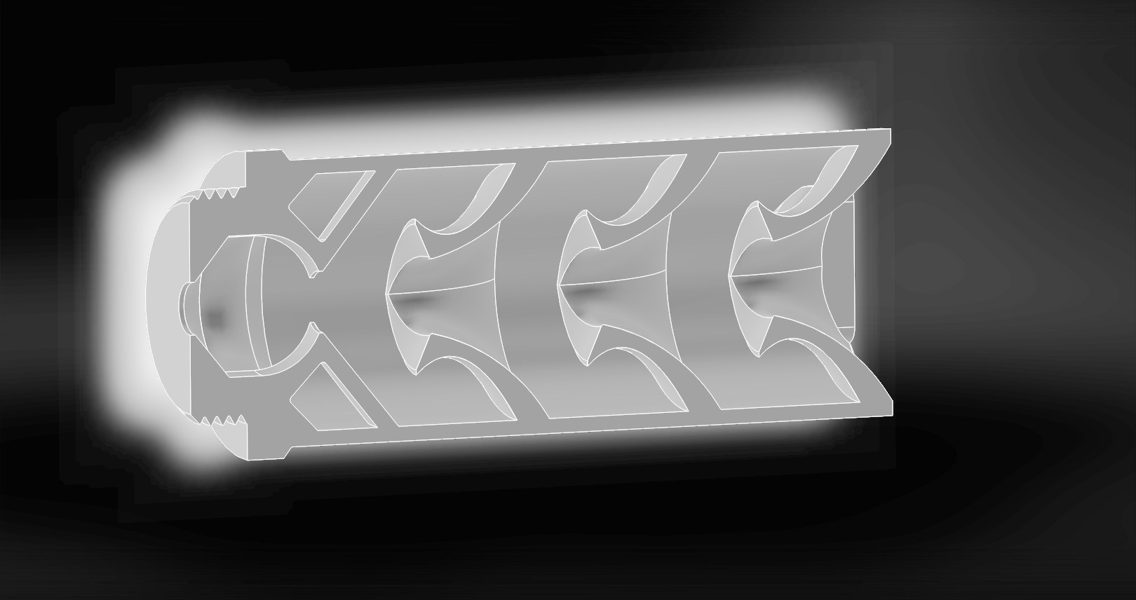
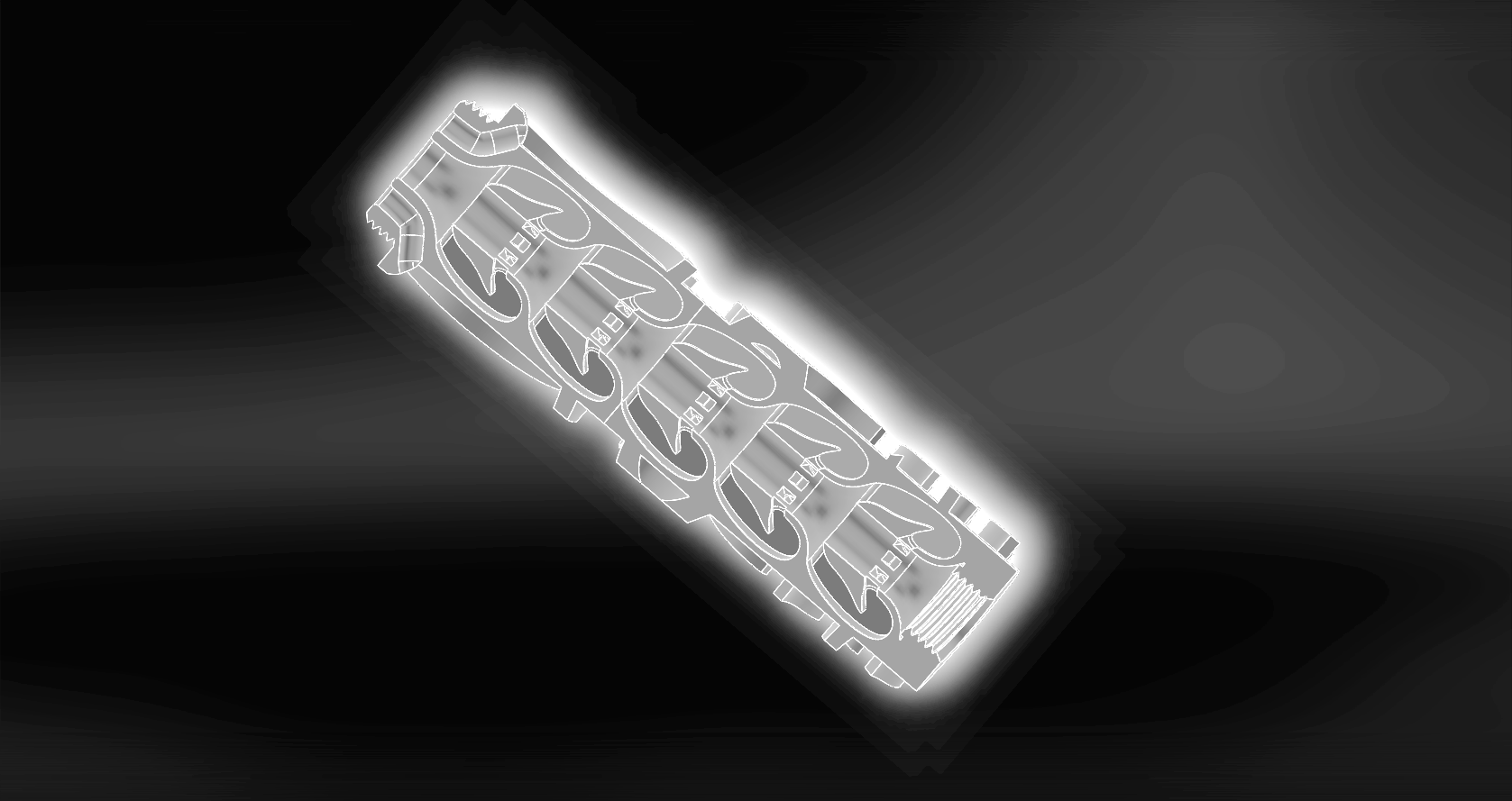
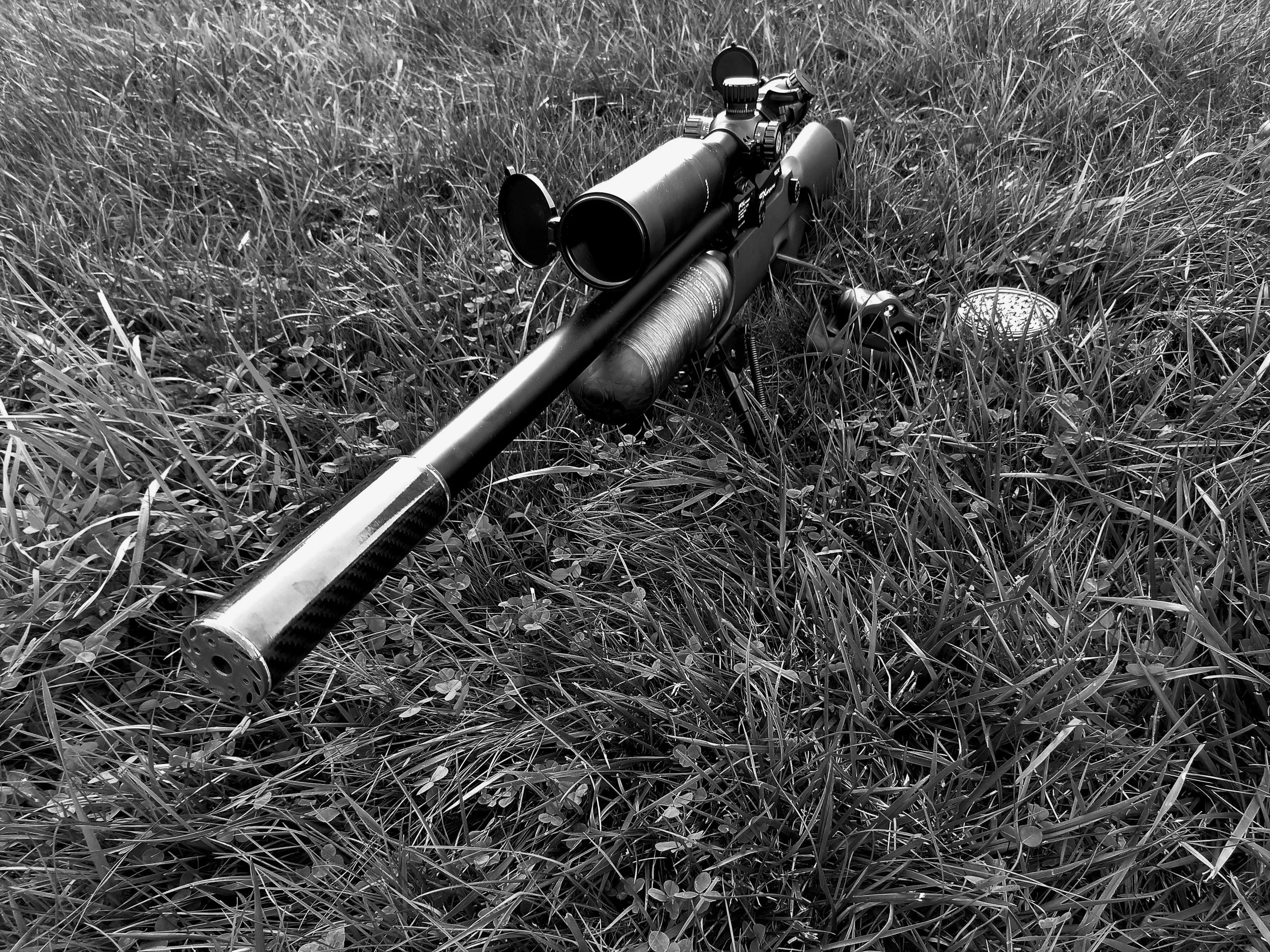
Put simply, the concept here is that the central core aerodynamically restricts flow to muffle the initial blast while the outer core allows flow as freely as possible while disrupting the pressure front responsible for the sound…… at least in theory, in practice things can be somewhat different.

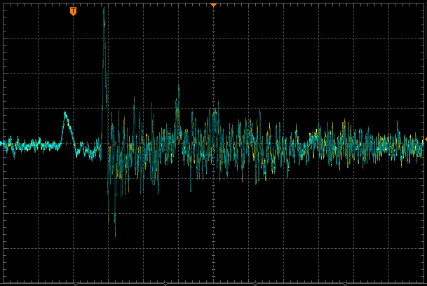
Here is the pickle: theory is where you understand things, but nothing works. Practice is where some things work, but you don’t understand why. I have a habit of combining theory and practice, where nothing works and I have no idea why. A hallmark of good science is a control, in essence a way to know if your hypothesis is valid or not. Instead of simply one control though, for optimum scienticiousness, I want three. I’ll then call up another buddy from STO to dig out the old impulse sound meter, an exotic device unlike conventional sound meters in that it measures peaks from short pressure waves rather than continuous sound, and test all four configurations. Speaking of which, all four configurations are as follows:

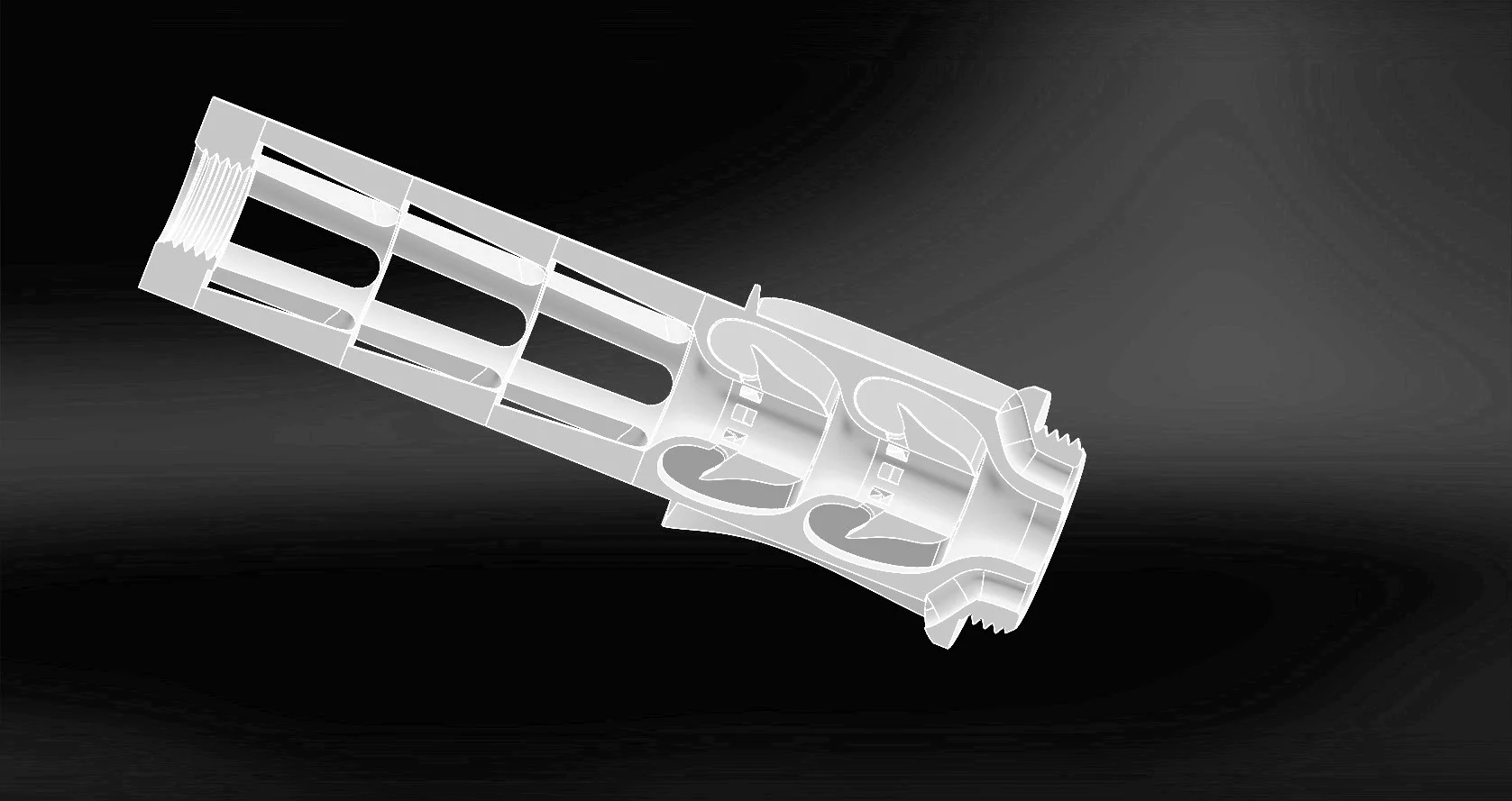
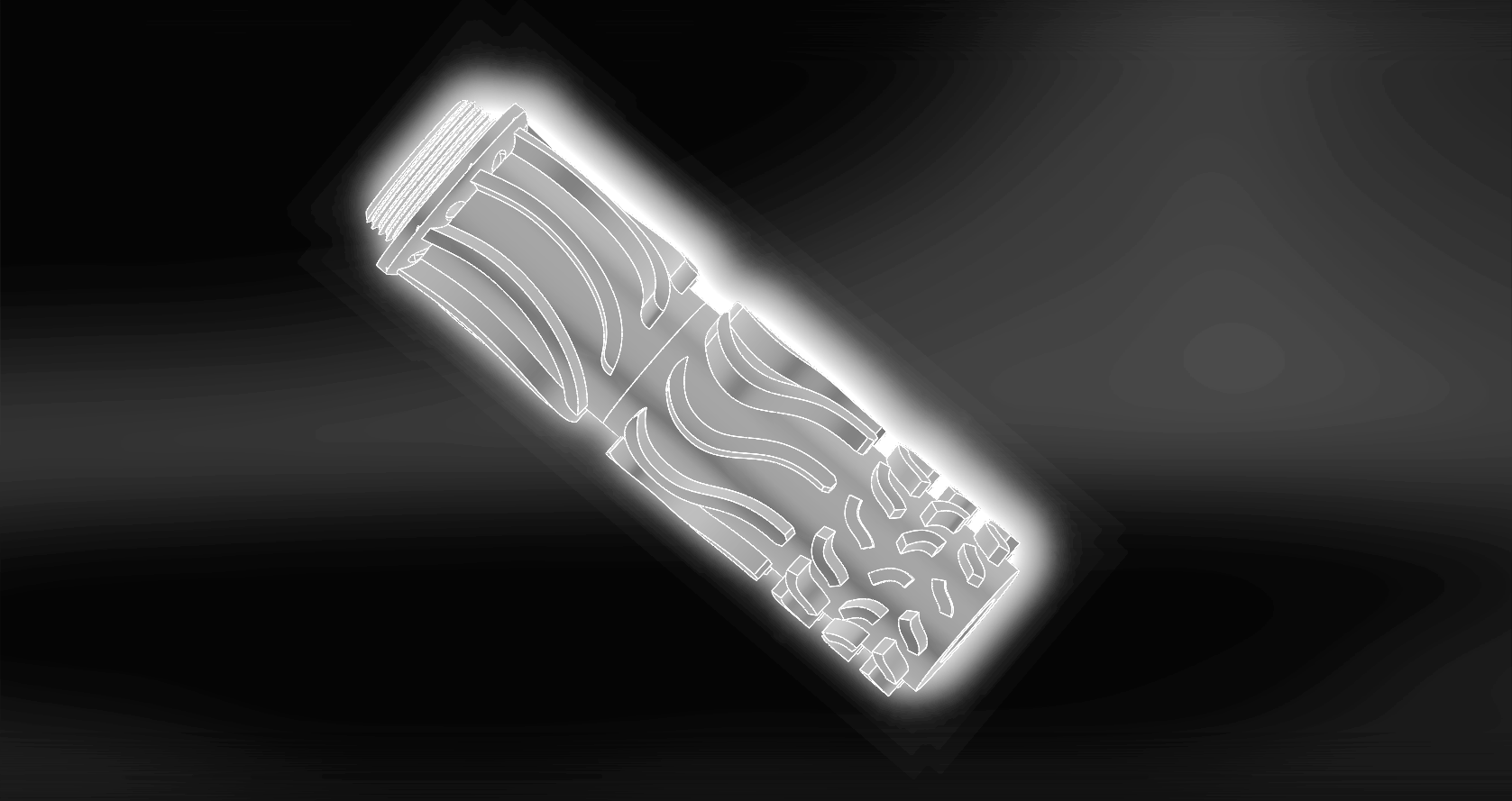
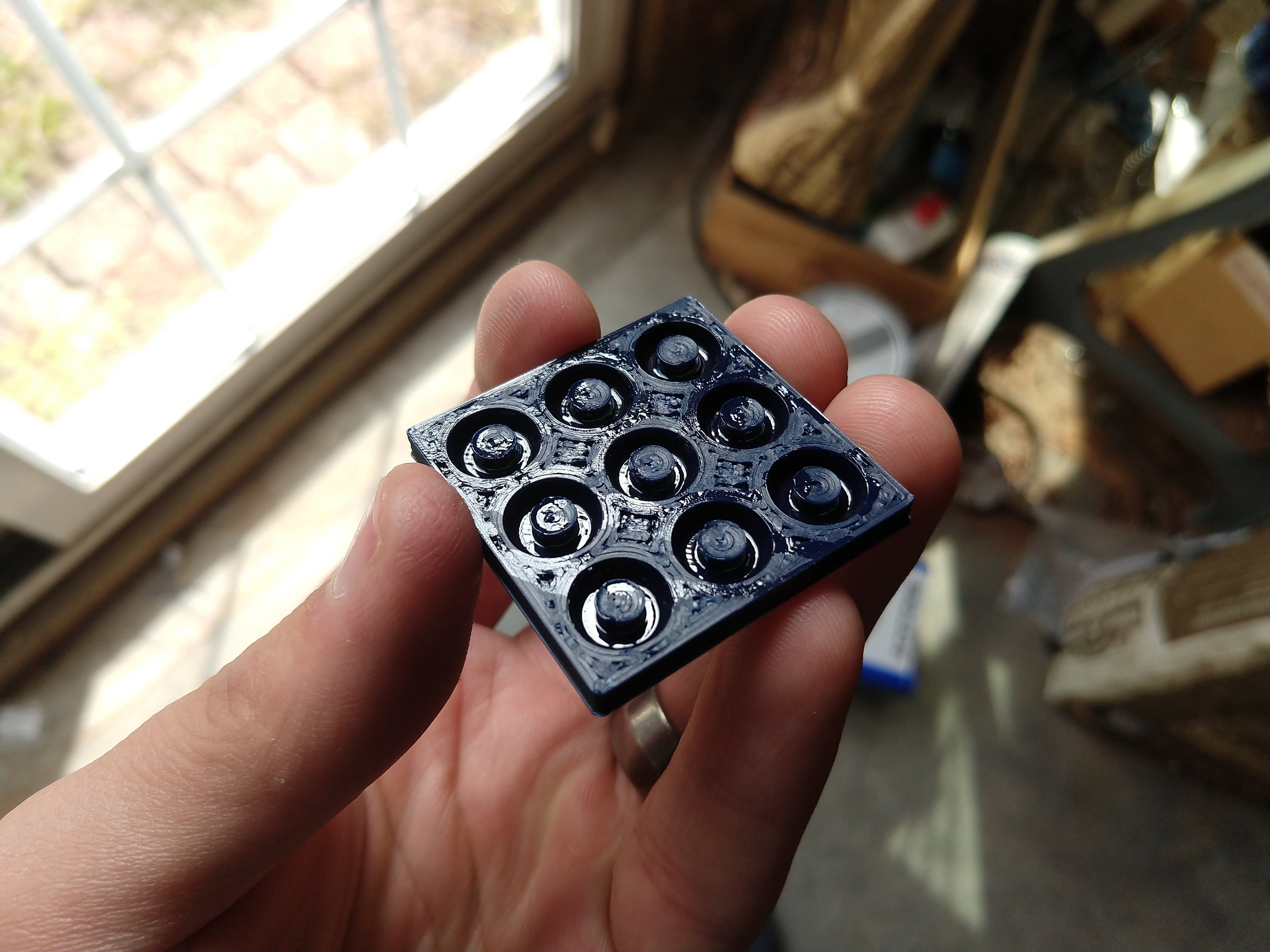
1) Very common in the firearms industry at the moment, even among some of the best brands, is the clipped conical baffle. This design has some, but not excessive, cross-jetting to disrupt forward flow. This design is also widely applied to both supersonic and subsonic suppressor designs, making it arguably applicable here. You might at this point be wondering why I’m not opting for the all too common traditional K-baffle, which is very effective in dealing with subsonic flow moderation. The answer is that the simple K-baffle isn’t that effective at sound moderation, comparatively speaking, although it is very easy to machine which explains part of its prevalence. The more complex and efficient K-baffles are very quiet, but induce a lot of cross-jetting which significantly negatively affect accuracy. They also tend to have tonal issues, so while the results are quiet on the meter they’re also shrill and unpleasant. Some companies, notably Dead Air Armament, have overcome this with much testing and design work but for obvious reasons I’d rather not have to extensively optimize an experimental control, because doing so would rather negate its value as a control as well as detract from the central experiment.

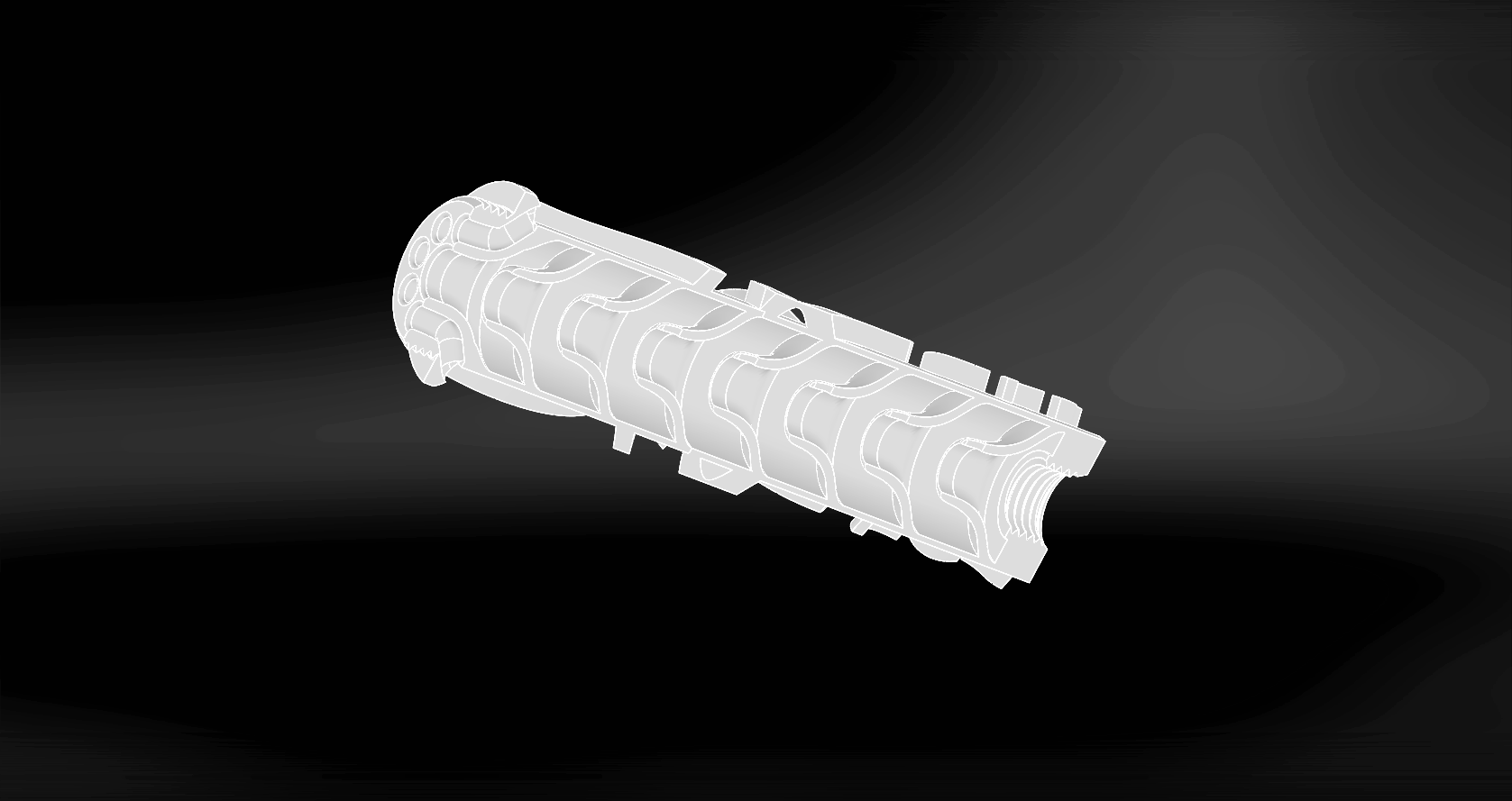
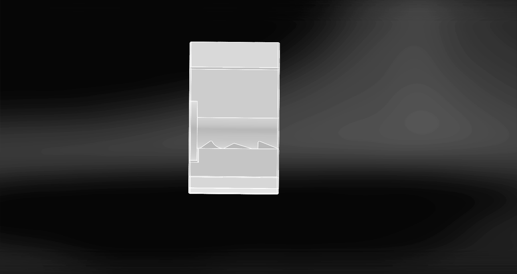
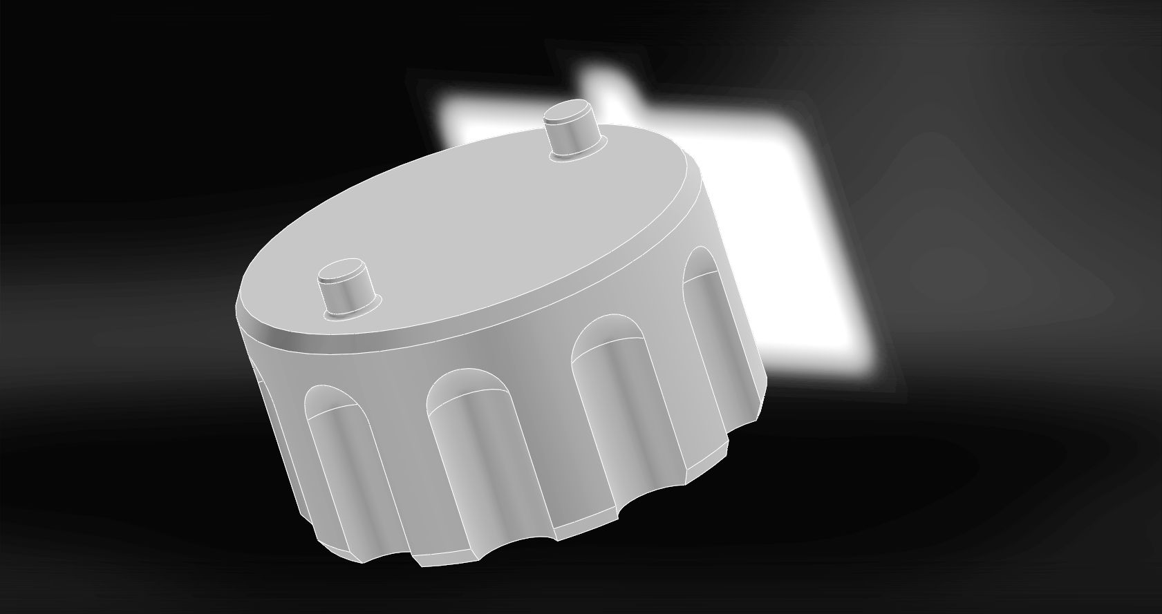
2) What if the clipped conical baffle works better than a Tesla Gas Diode at inhibiting forward flow in a suppressor, but is disadvantaged because it is shoved in a fixed-volume design? A scaled down clipped conical baffle stack used as the center core on the same outer core as the gas diode design would be a worthwhile control.

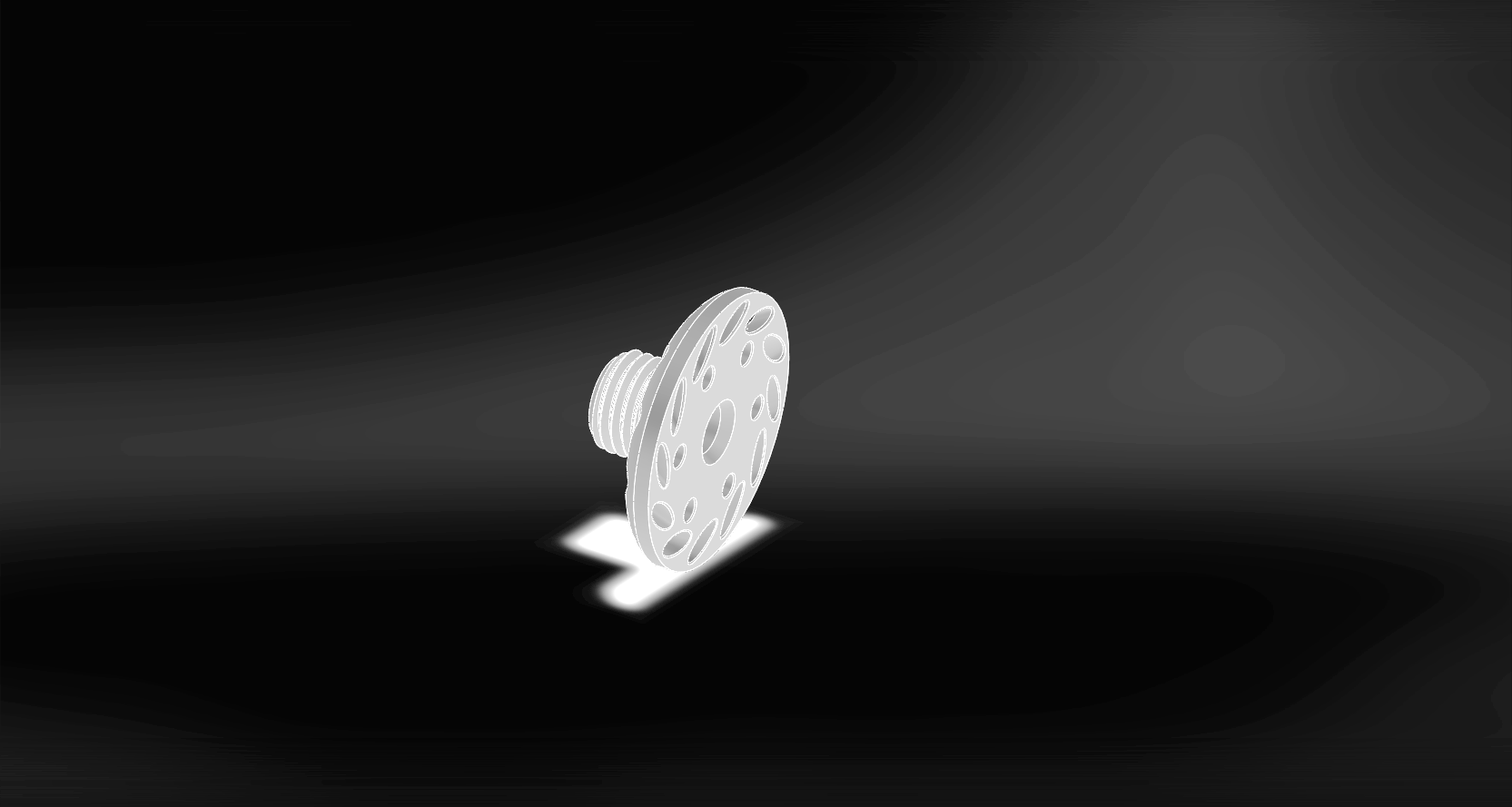
3) When everyone is doing one thing, and you’re doing something else, maybe that is because you’re a genius but more likely it is because you’re an idiot. I’d be foolish not to make a comparably sized design and pack it with an open-cell material like felt or foam which has worked so well for Huggett and DonnyFL. The architecture is trivial to design, so may as well run with it.

4) And, of course, the entree: my Tesla Gas Diode design. I have no doubt it’ll work, but whether or not it’ll work better than the other designs I have no idea.

And that is where things stand for now. There is a lot of time, design work, and testing between here and there. Also this blog post has dragged on long enough. So I’ll wrap it up here. In part two we’ll dive more into the gritty end of prototyping, a few more subtle elements of design, etc. Then in part 3 we’ll finally get to testing, results, and revisions.

The business end of the first gen gas diode moderator on the FX Crown. Note the lighter colored material at the interface between the carbon tube and ends. This is a glow-in-the-dark material, added for style, but could readily be any color/shade, i…

The business end of the first gen gas diode moderator on the FX Crown. Note the lighter colored material at the interface between the carbon tube and ends. This is a glow-in-the-dark material, added for style, but could readily be any color/shade, including that of the moderator core thus making it indiscernible. To the right we can also see a rangefinder and this gun’s preferred diet of JSB pellets.

Project - FX Crown Shroud Removal Tool

Silent Thunder Ordnance

Two FX Crown Shroud Removal Tools. Not strictly necessary, but as a quick and easy non-marring solution

Two FX Crown Shroud Removal Tools. Not strictly necessary, but as a quick and easy non-marring solution

Like I tell the wife: you want a quickie or the full two minutes? Well this, is that. I recently picked up an FX Airguns Crown, arguably the most accurate airgun. Unfortunately, with the factory moderator, it still has a bit of a bark to it. Step one in remedying this is is getting the muzzle cap off, which put up a fight, hence off to CAD to bang out a non-marring tool and….. SHAZAM! Cap is off. Should anyone else be wondering, the FX crown’s stock shroud is m27x1.5RH.

Where to from here? The simplest would be a couple nice clipped K-baffles to slip into the existing shroud when extended. A better solution though would be a bespoke moderator to take advantage of FX’s unique design. Watch this space, this project is just getting started.

A few minutes in CAD, and there it is.

A few minutes in CAD, and there it is.

Project - Baikal IZH-46M Gasket Replacement

Silent Thunder Ordnance

The repaired IZH-46M with one of the little blue gaskets just visible as a flash of blue at the breech. Also seen with one of our scalpeldashi in sapphire blue, a Kuru Toga Advance by Uni, and a tin if .177 Crossman Premier hollow point pellets.

The repaired IZH-46M with one of the little blue gaskets just visible as a flash of blue at the breech. Also seen with one of our scalpeldashi in sapphire blue, a Kuru Toga Advance by Uni, and a tin if .177 Crossman Premier hollow point pellets.

We’re not manufacturing these, check them out here.

The Baikal IZH-46M, I would argue one of the greatest airguns of all time. Why? Three reasons really: it is exceptionally good at what it does (shooting accurately), it is extremely convenient to shoot (no air cylinders to run out, or accessories to grab, just the gun and tin of pellets and you’re good to go), and it was very very modestly priced (about 500$ in its day). No surprise then it was an extremely popular airgun. Unfortunately, for reasons I’m not entirely sure of, they’re no longer readily available at least in the United States. If I were to guess, I’d say this was caused by some combination of the Russia embargo and Kalashnikov Concern’s financial turmoil. Either way, whole guns and spare parts have been rather hard to come by.

Despite my glowing praise for the gun, there is at least one minor shortfall: the breech can be “closed” such that the gun will discharge but not properly latched. Making this relatively minor oversight will result in popping out both breech gaskets, one of which will remain sitting on the bottom face of the breech if you’re lucky while the other will be injected into low earth orbit never to be seen again. (note on the IZH technical diagram this is part #19 and is labeled “packing ring” which is an accurate description) Thus did I fall into this trap inadvertently, and find myself in need of AT MINIMUM one breech seal. Of course two is one and one is none, so really half a dozen or so would be ideal with a way to acquire a potentially unlimited quantity.

A blow-up diagram of the BAIKAL IZH 46 M. Highlighted parts indicate the difference between the 46 and 46M variants. The part replaced in this blog post is labeled #19.

Here is the pickle though: while some clever engineering could have made this breech use standard O-rings, the 46 uses what so far as I can tell is a proprietary tapered gasket. Like most things engineered by Russians, it is a stuperb solution to the problem, possessing elements of extreme mechanical cleverness and a bizarre divergence from GMP.

So here I am, with one gasket and looking for an easy way to duplicate it. Whipping up a nice high-resolution silicone mould based off the one positive I luckily still had seemed the obvious choice, and so I prepped a container and the gasket. Unfortunately, as I discovered, the manufacturer most likely used a high sulfur urethane to make the gasket. This sulfur poisoned the platinum catalyst, and so the silicone failed to cure all around the o-ring. This was an abject failure.

The dastardly #19 gasket itself, here seen prepped for direct mould making. Little did I know…….

The dastardly #19 gasket itself, here seen prepped for direct mould making. Little did I know…….

I didn’t have much hope for this, but on a lark I modeled up a 9 cavity mould, printed it out, and figured if it failed at least it didn’t take that much time. Silicone was generously poured to fill, and left to cure.

A 3D printed mould. There is no way this could possibly work…… could it?

A 3D printed mould. There is no way this could possibly work…… could it?

I remember distinctly looking at this sad little pile of silicone thinking that there was absolutely no way it could possibly have worked…….

Here is the mould in its “poured” state. Silicone doesn’t stick to cardboard, so at least this scrap won’t have been wasted in this experiment.

Here is the mould in its “poured” state. Silicone doesn’t stick to cardboard, so at least this scrap won’t have been wasted in this experiment.

…..but sometimes life surprises you for the better. It is always better to be lucky than skilled, but when you’re struck with both in one moment, savour it as it is a rare beauty. Not only did it work, it worked fantastically well producing 9 perfect little gaskets.

No freaking way. IT WORKED!!!!!!!!!!! 9 perfect little #19 gaskets, perfectly formed, ready to nip off and install.

No freaking way. IT WORKED!!!!!!!!!!! 9 perfect little #19 gaskets, perfectly formed, ready to nip off and install.

A moment’s work with a Scalpeldashi (I always carry one for a reason) to pop one off and clean up the edges a smidge, and we’re in business.

Two little buggers nipped off with a scalpeldashi. The one of the left still needs a hint of trimming before installation, the one on the right is ready to go. I swear I’m not trying to whore this scalpeldashi, I really do carry it everywhere and us…

Two little buggers nipped off with a scalpeldashi. The one of the left still needs a hint of trimming before installation, the one on the right is ready to go. I swear I’m not trying to whore this scalpeldashi, I really do carry it everywhere and use it constantly. They are just so much thinner and sharper and better than Xacto blades, you have no idea.

SUCCESS! The fit was perfect and the seal was exceptional. Velocity, performance, and accuracy have all been fully restored, and now, at least for this part, there is a hypothetically limitless supply so I can go about losing them as fast as I care to. This begs the question: what other “irreplaceable” airgun seals might I someday blow which now I can replace? Time will tell.

The repaired IZH-46M with one of the little blue gaskets just visible as a flash of blue at the breech. Also seen with one of our scalpeldashi in sapphire blue, a Kuru Toga Advance by Uni, and a tin if .177 Crossman Premier hollow point pellets.

The repaired IZH-46M with one of the little blue gaskets just visible as a flash of blue at the breech. Also seen with one of our scalpeldashi in sapphire blue, a Kuru Toga Advance by Uni, and a tin if .177 Crossman Premier hollow point pellets.

Project - MPX Magazine Baseplate

Silent Thunder Ordnance

On the left is an original SIG SAUER MPX ban-state magazine, on the right a de-restricted magazine with full capacity.

On the left is an original SIG SAUER MPX ban-state magazine, on the right a de-restricted magazine with full capacity.

The SIG SAUER MPX, a very popular gun at the moment. There has, for somewhat baffling reasons to be honest, been a resurgence in the popularity of pistol caliber carbines. I personally had thought this trend had died in the 90s’ with the proliferation of rifle caliber platforms in comparable sizes. But for some reason, they’re back. Shooting the MPX, owned by a friend of the company, I can see why too: it can be shot at pistol-caliber-only ranges, it is reasonably accurate, it is cheap to shoot, it is essentially devoid of recoil, and it is fun.

A friend of the company recently visited with his MPX. Moving from a ban state to a free state, he has a surplus of neutered 10 round magazines, otherwise identical to their full capacity brethren, but limited by a follower block which is an integral part of the magazine floor plate insert. At 50$ per magazine, almost highway robbery for a plastic magazine if you ask me, his ban-state collection is worth the value of a whole new firearm.

Here we can see the follower block of a restricted SIG MPX magazine next to replacement MPX magazine floor-plate-inserts. These serve to control the spring and retain the baseplate without limiting capacity.

Here we can see the follower block of a restricted SIG MPX magazine next to replacement MPX magazine floor-plate-inserts. These serve to control the spring and retain the baseplate without limiting capacity.

SIG glues their baseplates on ban-state magazines, but a few firm taps with a mallet or a little judicious application of a heat gun will readily break them loose and allow them to slide off. You can then remove the magazine floor plate insert w/ restrictor. But how to hold the magazine baseplate on then? You could simply cut off the restrictor, however if you wanted to go backwards you’d then be stuck.

3D printing to the rescue! 15 minutes of design and a little printing later, there you have it: a brand new magazine floor plate insert to allow full capacity in a SIG MPX magazine.

A few firm taps with a mallet, maybe a little work with a heat gun, will remove the baseplate making the floor plate insert (restrictor) accessible. Pop it off, pop the new one in, and you’re good to go.

A few firm taps with a mallet, maybe a little work with a heat gun, will remove the baseplate making the floor plate insert (restrictor) accessible. Pop it off, pop the new one in, and you’re good to go.

For obvious legal reasons, if you are living in a ban state, we do NOT suggest you modify your magazines to give them an illegal capacity. In general it is our strongest recommendation, should you choose to enjoy firearms, you do so in a safe, responsible, and lawful manner.

Light of Xiuhtecuhtli

Silent Thunder Ordnance

Scale can be a difficult thing to comprehend and convey. Numbers, sizes, and distances beyond a certain point start becoming intangible. Can you really picture in your head what precisely ten miles or a million of something looks like? Probably not, it is just too big to wrap your head around in most cases. So by example, we try to make scale relatable. (more on units/scale at the bottom)*

Lance of Ra, 2.6 million candela lighting a moutain side 1.61 miles away. 

Lance of Ra, 2.6 million candela lighting a moutain side 1.61 miles away. 

The Lance of Ra is the most powerful LED thrower ever produced. At almost 3 million candela, it is good for 2 miles of ANSI throw. That is a lot, and in an attempt to demonstrate that we did some photography showing it illuminating a spot on a mountainside 1.61 miles away, paired of course with a satellite image giving a sense of the distance. 

Satellite map measurement for the above image of the Lance of Ra, showing a mountainside illuminated 1.6 miles away. 

Satellite map measurement for the above image of the Lance of Ra, showing a mountainside illuminated 1.6 miles away. 

But in that Lance photo there is another mountain ridge, just to the left of the one targeted. That ridge is part of a much MUCH larger mountain, which happens to be 4.27 miles away. Once again, for scale and measurement, we have a satellite image. 

A satellite image for the LoX image, showing the mountain 4.27 miles away. This is the furthest target we've yet found, as the LoX is capable of illuminating targets 9 miles away. 

A satellite image for the LoX image, showing the mountain 4.27 miles away. This is the furthest target we've yet found, as the LoX is capable of illuminating targets 9 miles away. 

If you hadn't guessed by now, we're going to illuminate that mountain. We even have enough power in the wash to illuminate the "near" mountain which is "only" 1.6 miles away. 

The Light of Xiuhtecuhtli, or LoX shown here illuminating a mountain top 4.27 miles away. In the wash on the right of the beam, you can see the 1.6 mile mountain from the Lance image illuminated with waste light. 

The Light of Xiuhtecuhtli, or LoX shown here illuminating a mountain top 4.27 miles away. In the wash on the right of the beam, you can see the 1.6 mile mountain from the Lance image illuminated with waste light. 

Welcome to the Light of Xiuhtecuhtli, named for the Aztec god of fire. With >50 million candela and >6000 lumens on tap, it is aptly named. This gives the LoX the power to reach out and touch targets 9 miles away (ANSI throw). It is a really unbelievable amount of performance, easily illuminating almost all clouds for example. Finding a place to really stretch its legs, and an evening clear enough to photograph it, was challenging. Ten mile visibility, the meteorological maximum air clarity standard, doesn't exactly occur between mountaintops nightly. 

What else is out there which compares to the LoX you might be asking? Not much actually, the LoX may be the most powerful flashlight ever made. (flashlight being defined as a hand held light source) The current most powerful common thrower is the BLF Giga Thrower. A very popular light, the BLF GT spits out about 1 million candela give or take and about 2000 lumens. The very similar Astrolux MF04 does a little better at about 1.3 million candela, again give or take. The Maxabeam is also eclipsed several fold, which is a mere 12 million candela. The closest light in performance is the 52 million candela Maxablaster, which has about the same throw but at a fraction the lumens. 

So where does the LoX stand? Right now it is a functional mule, a working test-bed for the optical and electronic architecture of the flashlight. This is why the numbers are all nicely rounded, this design is a long way from production, more performance may well be found if development is continued. Depending on customer response we may build this out into a complete product. 


*Candela is lux (light intensity) relative to distance, as lux obviously will vary wildly with distance. While for technical reasons it generally shouldn't be measured at 1 meter, as it produces inaccurate results, 1 candela is defined as 1 lux at 1 meter. ANSI throw is a standard for converting candela into beam distance, essentially a level playing field for comparing how far a light will project a beam. 

Product Introduction - Slingshots

Silent Thunder Ordnance

VHammer TTF in walnut and black paper micarta

VHammer TTF in walnut and black paper micarta

Funny enough, through a confluence of circumstances, we ended up making slingshots without ever properly introducing them. Things all got started when one of our members, a long time entheusiast, decided he wanted to design and 3D print himself a Bill Hays Harpy. A little strength and safety testing later (the slingshot failed at 344 pounds force) and other people started wanting them. This turned into a secret menu on our website devoted just to slingshots. Eventually, when we were ready, we made this public; a whole new category of product. 

Our Nit slingshot in lightning strike walnut. 

Our Nit slingshot in lightning strike walnut. 

What started with a single design quickly blossomed into our biggest product range. Slingshots allow for an incredible diversity of materials and shapes, so this really is a playground for us to play with design. 

Our Weaver slingshot shown here in translucent blue (near) and graphite over copper (far) 

Our Weaver slingshot shown here in translucent blue (near) and graphite over copper (far) 

Project - Custom Santoku

Silent Thunder Ordnance

Completed santoku with lightning strike walnut handle and copper ferrule. 

Completed santoku with lightning strike walnut handle and copper ferrule. 

Funny enough, if the snowy pictures don't make it obvious, this project was completed in December of 2018. Now summer, sweltering in heat and high humidity, it is refreshing to look at these pictures and write up the project. The purpose of this project was simple: provide a functional, elegant, and unique pair of gifts to two dear friends of the company for Christmas. To this end, a wickedly thin ground Japanese style kitchen knife with a little STO flair seemed like just the ticket. 

The first step was acquiring the stock blade. We went with a traditional japanese forged white steel blade done in the western inspired santoku style. These blades are ground for the hand, we went for right-handed, and are wickedly thin and sharp. How thin exactly? Almost zero ground, this example measuring approximately .08mm thick above the microbevel that forms the apex. The Japanese white steel, so named because of the color paper in which it is wrapped, is a low-alloy carbon steel fantastic for easily forming and holding incredibly sharp edges. 

The base blades, here with one handle removed. As you can see the original poplar handle and plastic ferrule are functional but leave much to be desired when it comes to beauty.

The base blades, here with one handle removed. As you can see the original poplar handle and plastic ferrule are functional but leave much to be desired when it comes to beauty.

These blades aren't sold naked though, in this form they come with plain poplar handles and plastic ferrules. Perfectly functional, but not very pretty. This is what we're here to change. Step one is getting the existing handle off. This proved harder than you might expect. Ultimately the easiest and safest method proved to be cutting the ferrule, cutting a groove in the back of the handle, and driving a cold steel chisel into said groove from the back. This way the wood is split from the blade without damaging it. Note, the blade was installed via a hot tang sunk into a hole drilled into the handle. This is a very firm method of installation, difficult to reverse by simply pulling the blade out. I should note that, at some point, one of us came to our senses and masked the blade so it wasn't quite so dangerous to handle. 

Drilling the walnut blank

Drilling the walnut blank

We cut blanks from some scrap walnut laying around, using the existing handles as a rough length guide. From there we had to drill out the tang part of the handle. This was something of a guess because we're going to burn in the tang later, so how large a hole you need to start with will depend on your specific wood's burn-out rate as well as tang width. You see half inch here, and next time around I'd go with considerably smaller as the tang sank in effortlessly. 

Lathe turning the walnut blank to maximum external dimensions. This is for bulk material removal only, as nothing on the handle is actually perfectly round. 

Lathe turning the walnut blank to maximum external dimensions. This is for bulk material removal only, as nothing on the handle is actually perfectly round. 

Once drilled, the lathe comes in handy to remove the bulk of material from the handle and ferrule area. It is worth noting that these handles aren't round when they're done, they have something of a D shape, and the ferrules are oval, but a lathe is a quick and efficient power tool to rough the oversize square blank down to the maximum dimensions of the oval and D respectively. 

Forming the ferrule area. 

Forming the ferrule area. 

A nice sharp chisel is the tool of choice to finish bringing the front of the handle to the oval cross section for the copper ferrule. Not pictured, a section of copper pipe was cut off using a pipe cutter, deburred, and crushed in the vice to form the correct oval shape. It was then traced onto the front of the handle. 

Pressing the copper ferrule onto the walnut handle for the santoku blade. 

Pressing the copper ferrule onto the walnut handle for the santoku blade. 

The ferrule was then pressed on. Remember snug is good. From there the handle was masked and the ferrule ground flush with the front of the handle and buffed. The ferrule was then masked and the handle taken over to the belt sander to sand down to finished D profile and brought up to 1000 grit. 

Heat burning the santoku blade into the handle. 

Heat burning the santoku blade into the handle. 

It is rather difficult to operate a hot knife, blowtorch, and camera at the same time, so you'll have to settle for a picture of the aftermath. Tangs on these knives aren't hardened. The blade was masked with a wet rag and the tang heated with a torch. We had expected with the density of walnut much pressing and maybe multiple attempts would be necessary. Surprisingly, it literally fell and sank in like this, no force necessary. Next time we'll start with a smaller hole. 

20180114_162321.jpg

Angry angry pixies were applied to the handle, lightning striking it, and leaving the scarring you see here. Not pictured was the time spent giving it one final go-over with sandpaper prior to finishing. For a finish we went with flax seed oil. This is food safe and polymerizes nicely, albeit slowly over the course of a week or two. The blade itself was coated, and it was poured and sloshed around inside the tang area as well assuring it'd be protected from corrosion. The one "down side" if you will is that flax seed oil isn't a neutral finish, it is quite yellow, and this can be seen on the blade (which was also coated) in the completion photoshoots. Now the knife is finished and ready for wrapping and gifting. 

Reflections on completion

Completed santoku with lightning strike walnut handle and copper ferrule. 

Completed santoku with lightning strike walnut handle and copper ferrule. 

Night Vision Spotting - IR Illuminators

Silent Thunder Ordnance

The compost pile, a favorite hangout for local rodents. Custom aspheric IR illuminator at only ~60 meters as seen through our digital night vision setup. 

A local predator shows up to hunt one of our spots. We left him to it. 

Rodents..... they're a problem. Poison creates ecological issues, trapping is indiscriminate, however night vision combined with an airgun can take a good bite out of the local population if you're so inclined. 

In this particular case we're using a digital night vision rig that sees into the infrared spectrum (hence the odd colors, leaves reflect IR light so appear white), which blissfully uses the existing scope via an adapter. And, of course, we're using an STO Custom IR illuminator. We'll need to test further, but with just a crescent moon out we could easily spot beyond 500 yards with it. This system on a more powerful rifle would be ideal for larger game at longer range, such as coyotes. 

Excellent brightness is the key to sharp high resolution images, in this case at about 60 meters to the target area, I had enough light and resolution to watch individual insects fly, and see the spider's eyes in the grass. Of course, using a lamp has an added benefit of lighting up the eyes of anything with tapetum lucidum. This includes our rodent prey. 

Turns out we weren't the only ones hunting rodents that night. This local cat showed up to hunt our spot, or perhaps we were hunting his. Not to fear though, we hit up a couple other spots and had a successful night.