Project - FX Crown Moderator (part 3)
Silent Thunder Ordnance
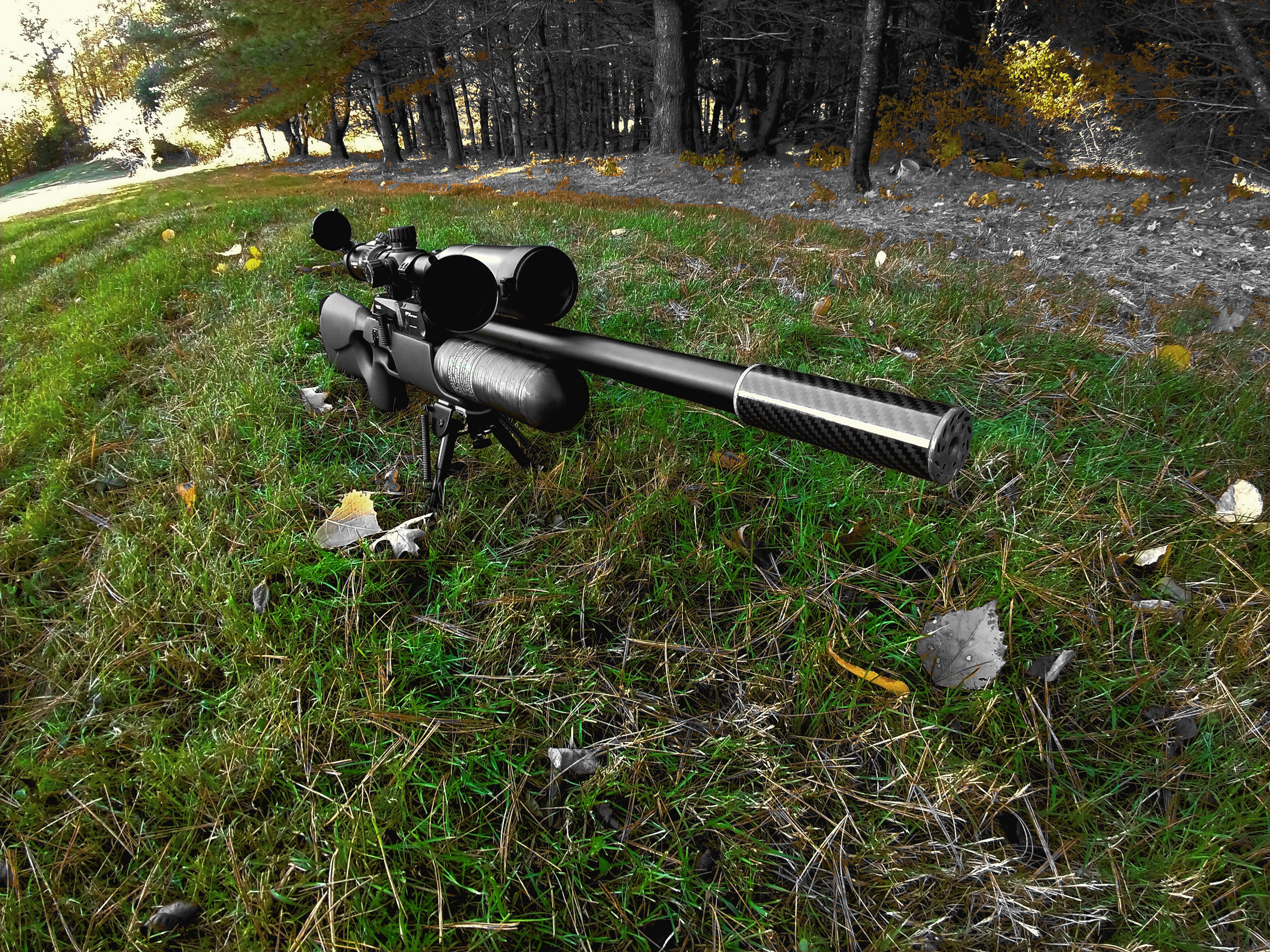
FX Crown with carbon fiber gas diode moderator
You can find part 2 here. This is the third installment of our attempts to make a novel and effective moderator for the FX Crown, the basis of which is a linear Tesla Gas Diode. The ideal is to generate an extremely compact, light weight, and POI-shift free with exceptional sound attenuation for its size. As an aside, we’ve received a lot of interest about our FX projects. The moderators in particularly have gotten quite some attention. If you have additional questions, please feel free to use the contact form in the top right hand corner of our website to get in touch.
It has been about two months since the last major update, and in that time we’ve gone through a couple different designs, tests, and revisions. Here we finally bring it all together and do one comprehensive analysis of all these evolutions. But first a question:
Why do many if not most moderators have the same architecture from end to end? It didn’t make sense to us either. This concept of flow-stopping at the rear and sound absorbers at the front is really the evolutionary theme with this test, because we have discovered it is very effective. It is more effective than either purely sound absorbing materials or baffles alone. Gas diodes revs.2, and 3 as well as LIM, use this to great effect. You first blunt the air flow with the baffles, and then you mop up the sound with the damping materials, in a manner of speaking anyway. Simple right? Regarding what materials we used, we did a bunch of experiments (not published) on all sorts of things, including several grades of the very popular felt. Ultimately specialty foam and rubber won out across the board, and so that is what was used in all subsequent tests.
Sound analysis
Same standard protocol and data capture/averaging as in the second test, although we switched pellets to JSB 18.13gn for this test. I do want to note quickly that atmospheric conditions, minute variations in the setup, pellet choice, and about a dozen other things will affect readings, which is why we retest our baselines EVERY SINGLE TIME. It is also why these numbers completely don’t line up with previous test numbers, as we wouldn’t expect them to and weren’t trying to make them. Conditions were about 31 degrees Fahrenheit, sunny, and with a light breeze.

FX Crown with shroud extended.
Stock Shroud Extended - 199.6
About what you’d expect here, obviously the loudest test. You can once again see the sound bouncing forward and backward in the tube as well. We’ve seen this all before.

The OG gas diode from our first test. Exceptional sound attenuation for its size and weight.
Tesla Gas Diode rev.1 - 138.2
This is our OG gas diode from the first test, the silver one for those paying close attention. As before, it extends the time frame where noise is observed, as well as blunting the initial peak. Not much else to say that hasn’t been said before. I don’t have a hypothesis about what that small initial positive peak is, it seems too close to the uncorking event to be the hammer slapping the valve, however I’d guess they are some other mechanical function of the gun. Either way, in this sample, it is very visible thus noted here.
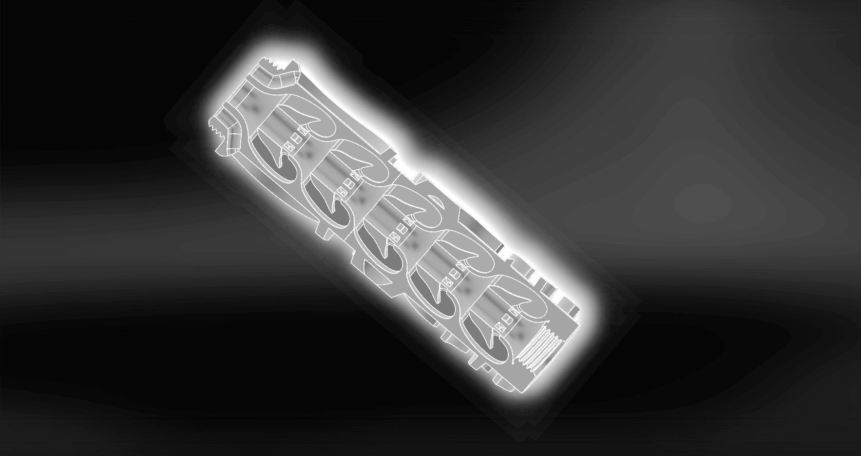
An image of the core of our rev.1 flow-through gas diode

Tesla gas diode rev.2, amazingly it is even quieter and lighter than rev.1
Tesla Gas Diode rev.2 - 112.0
The original gas diode had exceptional performance for its size and weight. What if you could cut that weight down by an additional 11% though, bringing it down to just 57 grams, all while attenuating sound even further? That is the concept which brought forward rev.2. It is still flow through, and still uses linear Tesla gas diodes at the rear, but after the diodes blunt the forward movement of the air, we applied sound attenuating materials so the subsequent draining of pressure out the muzzle end was even quieter. And it clearly worked. Beyond just lowering the peak output, it reduced the post-peak sound in both volume and duration. For people using cheap sound meters which can’t capture the peak, or cell-phone apps, this is probably what they’re measuring anyway. Regarding the core design, it is difficult to effectively show as it is a multi-part assembly which isn’t conducive to cross-sectioning in CAD. In brief though, at the rear, are the same flow-through structures on the outside and gas diodes in the core. Beyond that is a skeletal structure onto which the foam and rubber are installed. The same flow-through vortex cap as rev.1 is used at the muzzle end.
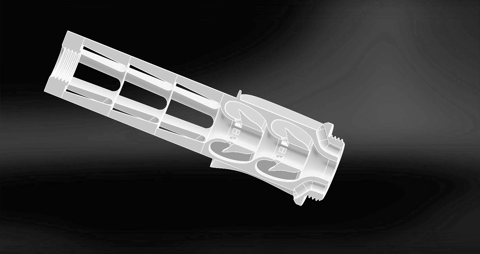
Rev.2 gas diode moderator. Not seen is the foam and rubber which populates the skeletal section at left, and further mutes the report.

Rev. 3 gas diode
Tesla Gas Diode rev.3 - 100.6
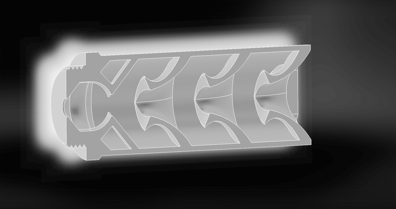
Like rev.2, this design uses gas diodes at the rear and a foam and rubber damper at the front. The major changes though are larger diodes, so no flow-through and a solid cap, along with a more aggressive rubber and foam section. It is a great design, but there are a few tweaks it could benefit from in regards to the damping section. We’ll get to the why of that in the next section, but suffice to say its minor improvement in sound attenuation is likely both caused and offset by some issues with the damper section. There is good reason to pursue this design further though, because the lack of flow-through means it could be redesigned for use on guns other than the crown, something we’ve gotten a lot of requests for. It is also worth noting that scale is a challenge with the rev.1 and rev.2 gas diodes, they are about as small as is possible without a major equipment reconfiguration. Omitting the exterior flow-through section has allowed these diodes to grow, which has other potential benefits.

Rev.3 gas diode. Not seen, but which would be to the right, is the foam and rubber assembly which acts after the gas diodes. This design uses a different cap (not pictured) as it is not flow-through.

LIM moderator sound profile
LIM - 91.2
LIM stands for Less Is More, the concept being maximum usable volume and a minimalistic design. It uses the same post-baffle dampers (not pictured) as the rev.3 gas diode. And I mean quite literally the exact same, we just swapped that section of the moderator for testing. The image below is actually outdated, as the baffle design has since been tweaked, however for now this design is a dead end. Why? Well moderator design is a balance between silence and accuracy-disrupting turbulence. In this case in its less-turbulent guise it was louder, and still caused accuracy issues, and in this test format it creates even more significant accuracy disruption but is a bit quieter. And that is really all there is to say about it.
LIM moderator core. This uses the same damper assembly and cap as the rev.3 gas diode. Unfortunately this design appears to be a dead end, as it induces accuracy issues.

If you’ll forgive the hasty scrawl, here is a quick target to confirm whether or not a design has accuracy issues. Note that LIM shows only 4 rounds, as it threw a flier so bad it was entirely off the paper.
Accuracy Analysis
Knowing that moderators, particularly overzealous ones, have a nasty habit of messing with accuracy, it is important to shoot some quick groups to ensure everything is working as it should. These groups were shot standing off a tripod which, if you’ve never done it, is more stable than hand holding but less stable than prone with a bipod. The range was 59 yards, the temperature was 31 degrees Fahrenheit, and there was a gentle breeze moving both the pellets and the target itself. Groups are all 5 rounds. It is worth noting that some of the shots tear the paper, and they have a tendency to tear it downward, but this is not keyholing I can assure you. Sighters were taken on another sheet, not shown here.
The rev.1 gas diode has already been extensively shot, so no need to revisit that here. So I started with the stock shroud as a baseline, which produced an extreme CTC distance of .67”.
The rev.2 diode did well, as expected, no notable POI shift and it was just a whisker over 1MOA here at .63” CTC. Omit the one high round, and it shrinks to .49”CTC. Certainly no accuracy issues here, and this design has been tested a bit before and should have no issue.
The rev.3 gas diode didn’t do as well, at .85” CTC, however this was almost certainly due, not to the diodes, but to too aggressive a foam and rubber damper section. The same issue reared its ugly head with the LIM which actually managed to suck some of the foam into the flight path, have it be trimmed by the pellet, and spit it out producing a flier which was off the paper. The less disruptive rev.3 diode didn’t send a pellet that wild, but clearly the damper section needs to be scaled back. This will cut sound attenuation to some extent, but will cure the accuracy issues.
LIM is just straight out. One round was off so far it missed the entire paper. Beyond that, the 1.07” CTC was less than inspiring, as was the POI shift. It serves as a great demo though regarding how a moderator can be made significantly quieter at the expense of accuracy.
And that is it for part 3. If this series continues to attract interest there will likely be a part 4. Let us know what you’re curious to see.

FX Crown with carbon fiber gas diode moderator