Airgun Moderator Design, Performance, and Development - Failure Analysis and Flow Factor (part 16)
Silent Thunder Ordnance
Catch the previous episode HERE.
So far, of the moderators allowed out into the wild, two have come back with catastrophic failures. Lets break down these failures, why they occurred, and how they can be prevented.
The first was over a year ago, one of the first 1/2UNF revs. of the Levitas ever allowed out into the wild. The rifle it was put on was a power setup which used, not air, but helium to maximize output. Helium, for those unaware, has lower molecular mass and a higher speed of sound than air*, resulting in more efficient propulsion; it is a better gas for producing power. The moderator failed around the edges of the front cap, leaving the core itself intact. This rifle was not suitable for the small standard flow Levitas, however the failure at that point showed a weakness in the design. Cores are 3D printed. While the wall thickness was sufficient there in the original design, front and rear faces were trued up on the lathe to ensure concentricity of the moderator. That skim cut had thinned the edges of the front cap enough that it became a failure point. The solution was threefold. First, thicken the front cap. Second, rib the front cap to provide additional strength and rigidity without occupying as much volume. Third, suggest that this was not the right moderator for this power level. We’ll get to the specifics of point three further below.
*CORRECTION A reader wrote in with a correction, thank you! Previously this read as “viscosity and speed of sound,” the viscosity element of which is very likely incorrect or at bare minimum is not a significant factor. In summary, at essentially atmospheric temperatures and pressures, helium has a slightly higher viscosity than air or nitrogen. Under the operating conditions found in PCP this likely remains, although I’m unable to find a citation for it. More information about the use of helium as a propellant can be found here: https://en.wikipedia.org/wiki/Light-gas_gun More information on the far-from-straightforward physics on the viscosity of gasses at varying temperatures and pressures can be found here: https://physics.info/viscosity/


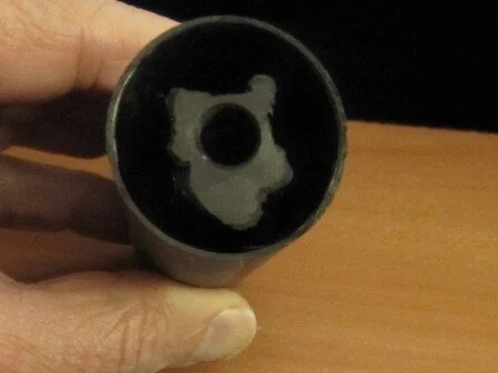
The second failure, pictured above, was more recent. It was a rev.2 Gladius running on a modified .308 Airforce Condor shooting slugs at 80FPE. What went wrong? According to the owner, after approximately 20 shots, the core failed and spit part of the second diode and the damping section downrange. (see images above) The failure was at the second diode in the struts above the body of the diode. While it is hard to see from the picture, there was no failure across a consistent layer. I also broke a couple of these struts to check for strength, and again, no materials issue is evident. This is good, it allows us to rule out a layer fault. The cross-section of these struts is conserved in this area, despite their organic shape, so they do not have a “weak point” per se which allowed different layers to fail on each of the six struts. For those who are familiar with FFF printing, I can hear the shouts already about the anisotropic properties of 3D prints. Let me stop you there though. The diode design places stresses on EVERY axis, there is no permissible weak orientation; a horizontal print orientation is not a solution. Furthermore the design is quite specifically engineered for adequate strength in this orientation. Finally, this material was specifically selected for cores because, among other reasons, it has excellent cross-layer strength and toughness. These material properties are determined in-house with a full suite of test equipment, instead of relying on manufacturer supplied data. This specific carbon fiber reinforced nylon was chosen very specifically for this application because of its exceptional material properties, which include a mere 20% increase in toughness by changing sample print orientations from vertical to horizontal; this is incredibly unusual among FFF materials and is not a typical property.
Everything in engineering is developed with what is called a “safety factor” or “FoS” which is represented by a number. There are slightly varying definitions of how it is determined, but the basic premise is that you have a number which represents the maximum load a part is expected to bear. Your safety factor is then multiplied by that maximum load, and you engineer the part to tolerate a load equal to this new value. Confused? So imagine you have a part which needs to hold 100 pounds. If you had a safety factor of 1, the part would be designed to hold 100 pounds and fail at 101 pounds. If you had a safety factor of 2 the part would be designed to hold 200 pounds, but still is only “rated” for 100 pounds. If you had a safety factor of 3 the part would be designed to hold 300 pounds, and again only “rated” (advertised for) handing 100 pounds. So on and so forth. It could be seen as essentially your margin for error. These safety factors can vary wildly between industry. Aerospace is notorious for having among the lowest safety factors, because these things need to get off the ground. Typical aerospace safety factors are 1.1 to 1.5. Structural members in buildings are typically 2. Pressure vessels are typically 3-4. It is rare to see a safety factor of 10 or greater. I design these moderators to all have AT MINIMUM a safety factor greater than 3.
So all that is well and good, why did this moderator fail? The answer is that, while the rifle was only producing ~80FPE much like the Crown, unlike the Crown it was using SUBSTANTIALLY more air to do so and had less volume (none) to defray that pressure. And that is the common thread here, with both these failures, it was a clear fault of mine: I failed to effectively convey what sort of power/flow the moderator was suitable for. And while design modifications could have prevented both failures, the internal core designs would not have provided good sound attenuation. And that makes this communication critical, not just to prevent failures, but to optimize sound attenuation. Previously I’d suggested people do a little “mental guestimation” based FPE output in relation to the size of the shroud, air efficiency, high drag barrels-projectile interactions (slugs), and shorter barrels for equivalent power. That broke down here. In fact, perhaps it never really functioned and we’d all just been getting lucky and/or banking on most people running airguns within a more modest envelope. So lets break this down in a little more empirical way.
Flow Factor
Empiricism in this case requires numbers, so how to quantify this air output or at least estimate it in a way which is reasonably accessible to everyone? Below is my attempt at this. The equation is somewhat simplified, but is derived from a larger formula based on the ideal gas law I use to calculate this myself. The units are a mess, but it allows us to relatively easily put a number to what sort of forces will be served to the moderator. The equation is as follows:
So this covers the air output, per shot, of the rifle with the units of BARcc/shot. Units must be maintained for this to work, pressures in BAR and tank volume in CC. Shots taken is, of course, the number of shots required to produce the pressure delta above. But there is one thing missing, and that is the shroud. This is where a compensation factor is required. If you have an efficient and reasonably large shroud (the FX Crown shroud is the standard here, having excellent flow into the shroud volume, before the moderator, and is 28mm OD), the equation spits out your final flow factor. But what if you don’t have a shroud, and are threading the moderator directly onto the barrel? Multiply your flow factor by 6. Why 6? Well it has to do with the relative volume of the FX Crown shroud and the gas-diode sections of my moderators. This may seem like a bit of a fudge, deriving this purely mathematically, but it is actually backed by testing on unshrouded rifles. (I can’t recall to what extent I’ve published that research, it is probably an anecdote somewhere in all this, although I reference the lessons learned CONSTANTLY by preaching the gospel of shrouds) I should note that the the application of the compensation factor is purely arbitrary, because I’ve standardized on the Crown. One could easily reverse this and have flow factor represent direct thread and a fractional compensation factor for shrouded guns. In this case though, it is my research, so my arbitrary decision goes. These numbers are only good for comparing with each other anyway, so it doesn’t really matter.
What if you have a shroud but it isn’t as good as a Crown’s? If you have a shroud which is a little small or a little inefficient (shorter length, smaller diameter, or air can enter the shroud but preferentially is directed into the moderator) multiply the flow factor by a number greater than one but less than three depending on your best guess for shroud efficiency. A good guess for most guns is usually 1.5-2. Keep in mind even very small shrouds can produce substantial improvements, so don’t discount them. Conversely, an even larger and more efficient shroud could potentially result in a compensation factor of less than one. And those improvements are seen in the final sound attenuation as well by the way; guns with worse shrouds or no shrouds will simply be a lot louder all else being equal. Yes you read that right, this to a limited extent is also a predictive model of airgun loudness.
So where does that napkin math lead us? Well that gives the FX Crown .22 running ~30FPE a flow factor of 460. It gives the FX Crown .30 running ~80FPE a flow factor of 1,111. A gentleman who provided data on his FX Impact .30 gave a number 725 for 74FPE. And how about a screwball, like the AAA Slayer .30 with a monster balanced vale and no plenum running 220FPE? 11,200. That is a big jump, as you might imagine.
But lets circle back to the point, how about these two failures, what were those rifles like?
Well for the first example, the modified Marauder, there are two big wrenches in the works: first is I don’t have the owner’s full specs list, and second helium behaves differently so it isn’t clear entirely how accurate this model could be. But for the sake of it, I pulled mrod numbers from a product listing and the pressure drop from the original correspondence and went for it. The result is a flow factor 14,822. You might be asking why that is higher than the Slayers? The simple answer is that not all gas released is converted to projectile energy. Far from it. This rifle consumed approximately 500PSI per shot from its cylinder according to the owner.
The second example the owner kindly provided me with detailed specifications permitting much more accurate results. It is an Airforce Condor fairly heavily modified with new barrel, tank, plenum, regulator, etc operating at 225BAR. (yes, that is plenum pressure) And, key here, no shroud at all. This all comes together to produce a flow factor of 15,300. For the astute among you, you’ll notice that means the rifle is consuming 3 times as much air per shot as the Crown for equivalent kinetic energy output and with an equivalent barrel length. Now to be clear, slugs (what the Condor is pushing) do have more barrel drag and lack the self-sealing skirt of pellets so will not be as efficient, but the efficiency gap here is still tremendous. Even I, an owner of an airforce rifle and bemoaner of their inefficient air usage, was startled when all those numbers fell out.
And that, as they say, is that. I hope it provided a valuable little peek behind the curtain on how some of this stuff works from an engineering perspective as well as how these things can fail. More importantly, I hope that going forward this provides a bit of a yardstick to help people select moderators, from any/every brand, which are better optimized for their rifles. And finally, I hope this provides some predictive value for people out there looking for a quiet rifle, because while this model certainly isn’t the last word in sound production/attenuation, does provide a good indication of what to expect.
Next up in the project will be a post about the sound profile of target impacts. Should be a little more casual than all this.